Before continuing on if you don’t have an understanding of shear and moment diagrams and how to calculate area moment of inertias. I strongly recommend you look at those pages before continuing.
Bending of a part is a very common occurrence, and being able to calculate bending stresses will help an engineer determine if a design is feasible, or if it instead needs to be modified. During bending, in most cases a normal stress in tension and compression is created along with a transverse shear stress. The only time shear would not be a factor is if the beam is only under a moment. Transverse shear stress will be discussed separately.
Normal stress on a beam due to bending is normally referred to as bending stress. First off, bending stress consists of a compression stress along with a tensional stress. The type of stress changes at the neutral axis. There is no normal stress at the neutral axis. The neutral axis is always located at the beams centroid, which means it’s not always directly in the center of the beam. For any situation of bending, the higher stress is on the point farthest away from the neutral axis. Refer to the figure below.

Depending on the beams setup, the maximum stress would be located at different points of the length of the beam. This point can be determined from the moment diagram which will show the point along the length of the beam that has the greatest moment. However, if the beam is a cantilever beam then the highest stress would always be located at the wall where the beam is connected, while if the beam is in simply supported configuration, then the highest stress would be half way down the length of the beam. To calculate the normal stress on a beam equation 1 would be used.
(Eq 1) $σ=\frac{Mc}{I}$
$M$ = Moment
$c$ = distance to neutral axis
$I$ = area moment of inertia
Unsymmetric Bending
Unsymmetric bending is bending that would occur in both the x and y axis. Due to this there will be a moment created in both direction and both the x and y area moment of inertias would have to considered. To calculate the stress equation 2 would be used, and to calculate the angle offset of the neutral axis equation 3 would be used.
(Eq 2) $σ=-\frac{M_xy}{I_x}+\frac{M_yx}{I_y}$
$σ$ = Bending Stress
$M_x$ = Moment in the x-direction
$y$ = distance to neutral axis on the y axis
$I_x$ = Area Moment of Inertia x-direction
$M_y$ = Moment in the y-direction
$x$ = distance to neutral axis on the x axis
$I_y$ = Area Moment of Inertia y-direction
(Eq 3) $\tan{α}=\frac{I_x}{I_y}\tan{θ}$

Composite Beams
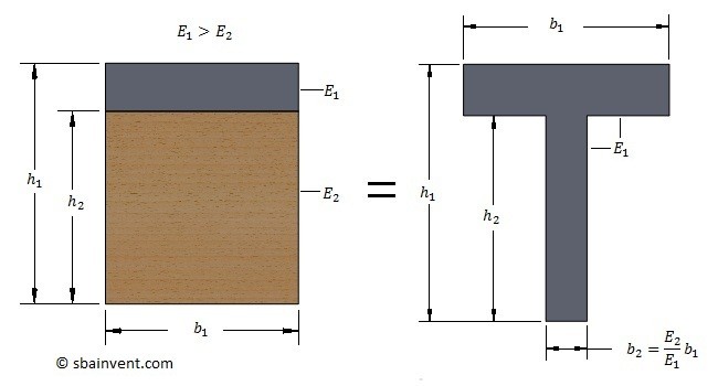
So far all I have talked about are beams that consist of one material. However, there can be cases when a beam could consist of more the one material. In other words it would be composite beam. Now if you were start using the equations that I have in previous section without considering that the beam is made out of a composite material, you would not get the correct answer. The reason why is because each material has its own stiffness, which means the beam is going to behave differently than if it was made completely out of one material. In order to solve a problem like this the beam would have to be manipulated. One of the easiest ways to manipulate the beam is to change it so that it is made of the same material, but has the same stiffness as the composite beam. To do this you would have to take the ratio of the young’s modulus of the beams; equation 4. Once you have that ratio you can then change a dimension of one of the material sections, which would in turn change the beam so that it takes in consideration of both materials.Refer to the example below.
(Eq 4) $η=\frac{E_1}{E_2}$
$E$ = Young’s Modulus