Axial loading occurs when a force or pressure is applied parallel and on the centroid axis of an object. Refer to the image below to see what axial loading is. With any strength of materials problem statics should be used to create a free body diagram, regardless of how simple that problem looks. This is done to make sure all forces sum to zero so that something isn’t missed. A free body diagram for an object under axial load is seen below. Notice that on the free body diagram the force P cancels itself out causing the forces to sum to zero.
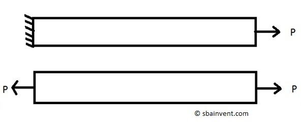
Now that the free body diagram shows that the forces sum to zero, the stress for the axial loading can now be calculated. Recall from the stress section that a stress is calculated by dividing a force by an area. For the above image the cross-sectional area that would be used is the cross-sectional area that is perpendicular to the load P. Refer to the equation below. The resulting stress will be considered a normal stress not a shear stress.
(Eq 1) $σ=\frac{F}{A}$
σ = normal stress
F = force
A = area
When calculating the stress due to an axial load the stress would be constant when the cross-sectional area remains the same. However, if the cross-sectional area changes than the stress will change accordingly. The stress will get lower for larger cross-sectional area and in comparison the stress will higher for smaller cross-sectional areas.
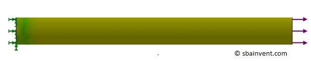
Now there is a certain case where the stress will vary even though the above equation states that it should be uniform through the part for a constant cross-sectional area. This happens when the end of the object is fixed. This is known as Saint Venant’s principle and can only be seen when an FEA is ran as seen in the image below.
Now remember from the Hook’s Law section that the deflection can be calculated if the Young’s Modulus of the material is known. To calculate the deflection of a part caused by an axial load the equation below would be used.
(Eq 2) $δ=\frac{FL}{AE}$
δ = deflection
L = length
E = Young’s Modulus
In addition to a calculating deflection and stress, the stiffness of the part can also be calculated by using the equation below. Stiffness is used to relate the deflection to the force required to deflect the object. Determining the stiffness will allow you to determine the deflection of a part that is made out of multiple materials. Also, it is used to calculate the natural frequencies of the part.
(Eq 3) $k=\frac{P}{δ}=\frac{AE}{L}$
k = stiffness
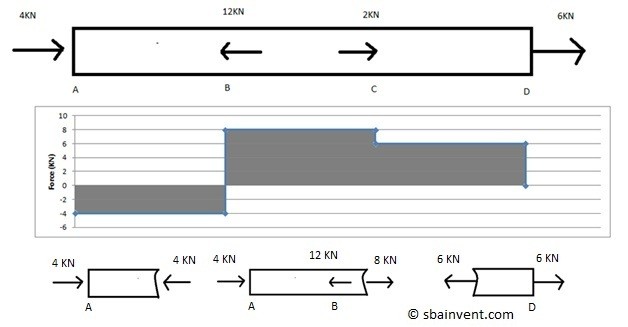
Multiple Loading
Now there are also cases when there could be multiple loads on part instead of a single load. To solve this type of problem you will need to create a free diagram. In this case multiple free body diagrams that relate to each other would be used. Remember the forces must sum to zero. To see how to do this refer to the image below.