To develop a flow meter you can use a combination of Bernoulli equation and the continuity equation. Recall that the general Bernoulli equation along a streamline is represented by the following equation.
(Eq 1) $p_1+\frac{1}{2}ρv_1^2 + γz_1 = p_2+\frac{1}{2}ρv_2^2 + γz_2$
$p$ = thermodynamic pressure
$ρ$ = fluid density
$v$ = fluid velocity
$γ$ = specific weight
$z$ = fluid height
Remember to use the above equation you will need to make a few assumption. First, the fluid must be inviscid. Second, the flow must be steady. Finally, third, the fluid must be incompressible. If any of these assumptions cannot be satisfied than using the above equation will result in inaccuracies.
In addition to Bernoulli equation, you will also need to use the continuity equation. The continuity equation relates the fluid’s velocity to its flowrate.
(Eq 2) $Q = A_1v_1 = A_2v_2$
$A$ = cross-sectional area
$Q$ = flowrate
Flow Meter Equation
You can determine the flow of fluid through the use of both the Bernoulli equation and the continuity equation. To do this you need to use a pipe that has two different cross-sectional areas. Refer to the figure below.
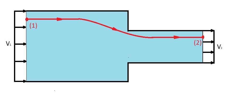
The above represents a simple method to measure flow. In order to measure the flow you will need to determine what the thermodynamic pressure is at the two points by using a pressure gauge that is perpendicular to the fluid flow.
Now you should notice that this type of problem is basically the same type of problem you would encounter for confined flow. As a result the general Bernoulli equation would become the following.
$p_1 + \frac{1}{2}ρv_1^2 = p_2 + \frac{1}{2}ρv_2^2$
Next, the question is how to determine what the flowrate of the fluid is due to the thermodynamic pressure change between to the two points. To answer this we have to look at the continuity equation. From the continuity equation the following can be stated.
$v_1= \frac{Q}{A_1}$
and
$v_2 = \frac{Q}{A_2}$
Plugging the above into the Bernoulli equation will result in the next equation.
$p_1 + \frac{1}{2}ρ\left(\frac{Q}{A_1}\right)^2 = p_2 + \frac{1}{2}ρ\left(\frac{Q}{A_2}\right)^2$
Now we can solve for Q to derive the equation to find the flow rate of the flow meter.
(Eq 3) $Q=A_2\sqrt{ \frac{2(P_1-P_2)} {ρ\left[1- \left( \frac{A_2}{A_1} \right)^2 \right] } }$
Types of Flow Meters
As I mentioned above the design of a basic flow meter is fairly simple. You do however need to think about how you design the flow meters transitions between the two different cross-sectional areas. If the change is to abrupt additional losses will develop within the flow meter decreasing its accuracy. First, let’s take a look at the simplistic type of flow meter an orifice flow meter.
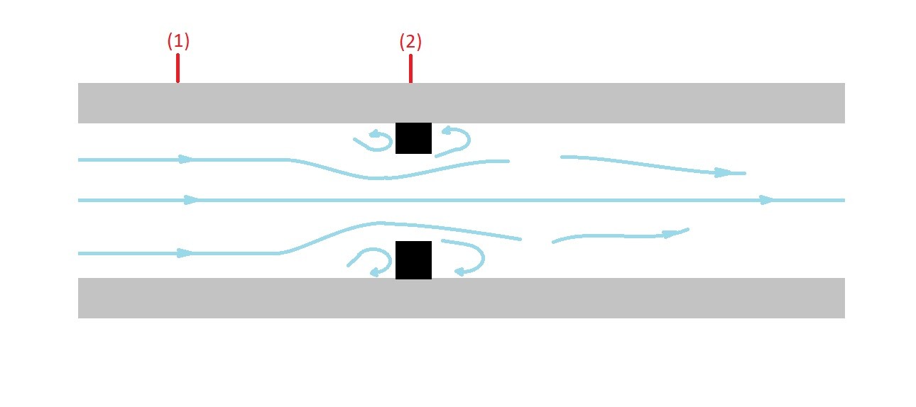
The above image is an example of an orifice flow meter. An orifice flow meter is has a very abrupt change in the cross-sectional area. Due to this fact areas of low pressure will develop. These low pressure areas will disturb the streamlines of the fluid flow causing inaccuracies in the flow measurement.
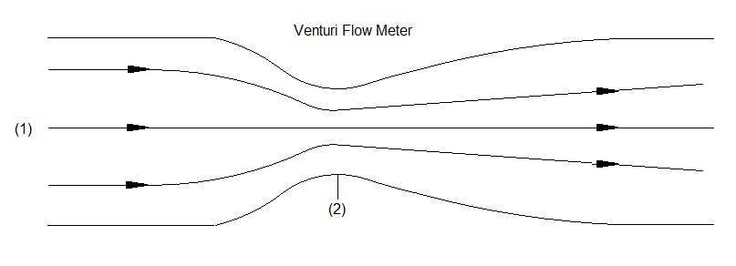
On the other hand if you were create a smooth transition between the two cross-sectional areas the low pressure areas can be eliminated. This in turn will prevent the fluids streamlines from being disturbed allowing a more accurate flow measurement. An example of this type of flow meter is a Venturi flow meter.