General plane motion occurs when a rigid body experiences both rotation and translation at the same time. There are two methods that can used to solve a general plane motion problem. You can use absolute motion analysis or relative motion analysis.
Relative Motion Analysis
In a previous article I discussed absolute motion analysis. In order to use absolute motion analysis you have to be able to solve the problem with one point of reference. However, there could be cases where you will need more than one frame of reference to solve the problem. If this is the case than you would need to use relative motion analysis.
Position
When you are using relative motion analysis you will need to have at least two frames of reference. Let’s use the image below as an example. The first frame of motion is the x, y coordinate system is based off the absolute position of points A and B in respect to the fixed position O. Furthermore, you will need to determine a base point. In this case the base point will be point A. The base point will normally have a known motion where an additional coordinate system x’, y’ will translate in respect to the fixed x,y coordinate system. The base point, however, will not rotate with the rest of the body.

(Eq 1) $r_B=r_A+r_{B/A}$
A real life example of where relative motion analysis can be applied is a four bar linkage. A four bar linkage typically consists of a crank link, a rocker link, a coupling link, and a ground link. The crank and the rocker will be connected to two different pinned points that are fixed to the ground link which has no motion. Due to this fact the crank’s and rocker’s motion will be rotation about a fixed axis. The coupling link however will have a complex translation motion that is dependent on the length of the rocker and the crank. Below is an example of a simple four bar linkage.
Example
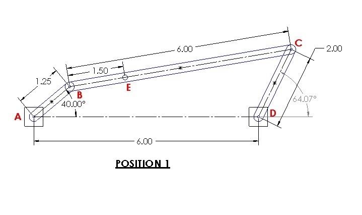
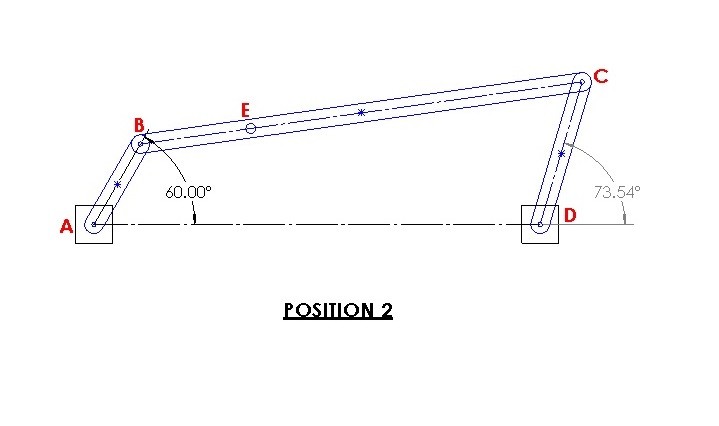
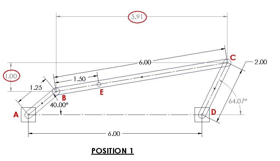
A four bar linkage moves from position 1 to position 2. Determine the displacement of position E.
Solution
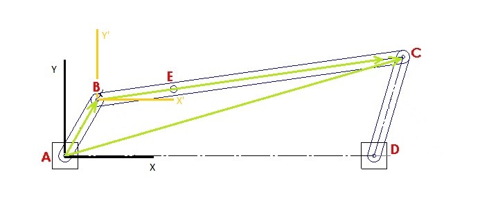
Step 1: First, for right now ignore point E. You will not be able to determine point E’s position without first determining the relative position of coupling link BC. To solve the problem you will need to choose two frames of reference. One of the frames of reference needs to be fixed and you need to be able to determine an absolute position from it. The next frame of reference will be your base point which is where the relative coordinate system will be based from. For this problem I will choose point A as my fixed position, and I will choose B as my base point. Choosing these point will result in the position vectors seen below.
Step 2: Determine the absolute x, y coordinate values for points B and C.
Position 1
$B_1=1.25~cos(40)i+1.25~sin(40)j=0.96i+0.80j$
$C_1=(2~cos(64.07)+6)i+2~sin(64.07)j=6.87i+1.80j$
Position 2
$B_2=1.25~cos(60)i+1.25~sin(60)j=0.63i+1.08j$
$C_2=(2~cos(73.54)+6)i+2~sin(73.54)j=6.57i+1.92j$
Step 3: Determine the relative position of link BC using equation 1. As a sanity check if you take the magnitude of relative position it will equal the length of link BC.
$r_{C/B}=r_C-r_B$
Position 1
$r_{{C/B}_1}=(6.87-0.96)i+(1.80-.80)j=5.91i+1j$
$BC=\sqrt{5.91^2+1^2}=6$
Position 2
$r_{{C/B}_2}=(6.57-0.63)i+(1.92-1.08)j=5.94i+0.84j$
$BC=\sqrt{5.94^2+0.84^2}=6$
Step 4: Once you have determined the relative position of link BC you can now determine the relative position of point E. In order to do this you will need to recognize that the relative position C/B is the distance from point B to point C in x’, y’ coordinates. Refer to the image below for position 1.
As a result you will be able to determine the offset angle of link BC. Which In turn will allow you to determine the relative position of point E.
Position 1
$θ_1’=tan^{-1}\left(\frac{1}{5.91}\right)=9.6^o$
$E_1 = 1.5~cos(9.6)i+1.5~sin(9.6)j=1.48i+0.25j
Position 2
$θ_2’=tan^{-1}\left(\frac{0.84}{5.94}\right)=8.05^o$
$E_2 = 1.5~cos(8.05)i+1.5~sin(8.05)j=1.49i+0.21j
Finally, the displacement of point E can be found by subtracting position 1 from position 2.
$E_{1-2}=(1.49-1.48)i+(0.21-0.25)j=0.01i-0.04j$
or
$E_{1-2}=\sqrt{0.01^2+.04^2}=.041$ ![]()
Velocity
As the bars of the linkage in the example above move there will be a certain velocity at each point of interest. Before discussing linkages further lets go back to the vector image at the top of the page. The observer the reference point O will observe a unique velocity at points A and B. Further more these velocities can be related to each other through the relative position vector $v_{B/A}. Finally, if you were to take the derivative of equation 1 in respect to time you would produce a relative velocity equation.
$\frac{dr_B}{dt}=\frac{dr_A}{dt}+\frac{dr_{B/A}}{dt}$ result in
(Eq 2) $v_B=v_A+v_{B/A}$
Now, since we are analyzing rigid bodies, the variable $v_{B/A}$ will need to be related to the angular velocity ϖ of the body. This relation will result in the equation below.
$v_{B/A} = ϖ~×~r_{B/A}$ Be aware that this is a cross-product of two vectors.
(Eq 3) $v_B=v_A+ϖ~×~r_{B/A}$
where
$v_B$ = velocity of point B
$v_A$ = velocity of the base point A
$ϖ$ = angular velocity of the body
$r_{B/A}$ = relative position vector from point A to B
Instantaneous Center of Zero Velocity
In addition to using equation equation 3 to find the velocity at point B, as well as the angular velocity of body AB, you could also find the instantaneous center of zero velocity of the two velocity vectors. By doing this it allow you to modify equation 3 so that you don’t have to perform a cross product.
(Eq 4) $ϖ_{AB}=\frac{v_A}{r_{A/IC}}=\frac{v_B}{r_{B/IC}}$
In order to find the instantaneous center of zero velocity you will need to send out imaginary lines from the two points that are perpendicular to the velocity vectors. Hence, where the two lines intersect is the instantaneous center of zero velocity (IC).

Once you know the distance to the point of zero velocity you can use equation 4 to find the angular velocity of body AB as well as the velocity at point B; if you know the velocity at point A. In certain cases the velocity vectors would be parallel to one another. As a result this will cause $r_{A/IC}$ and r_{B/IC} to equal ∞, which means that at that moment there is no angular velocity present and $v_A=v_B$.
Example
Let’s revisit the linkage problem in the first example. For position 1 the angular velocity ϖ of link AB is 20 rad/s. Determine the velocity of points B,C and E as well as the angular velocity of link BC and link CD. All dimensions are in inches.
Solution
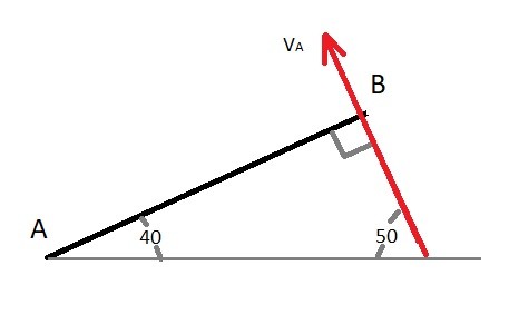
Step 1: We already know that the angular velocity of link AB is 20 rad/s. Using this information we can determine the resulting tangential velocity at point B.
$v_B = ϖ_{AB}~×~r_B$
$v_B=20~×~(1.25cos(40)i+1.25sin(40)j$)
$v_B=20~×~(0.96i+0.80j$)
$v_B= -16i + 19.2j = 25 \frac{in}{s} $
Step 2: Since we have determined what the velocity is at point B we can now find the velocity at point C as well as the angular velocity of link BC by using equation 3.
$v_C=v_B+ϖ_{BC}~×~r_{C/B}$
$v_C = -16i+19.2j+ϖ_{BC}k~×~(5.91i+1j)$
$v_C = -16i+19.2j-5-ϖ_{BC}i+5.91ϖ_{BC}j$
or
$v_{C_i}=-16-ϖ_{BC}$
$v_{C_j}=19.2+5.91ϖ_{BC}$
Step 3: Notice that when the velocity equation for link BC is separated into its x, y scalar components that there are currently to many unknowns to solve for. However, the velocity equation for link CD can also be used to find the velocity at point C.
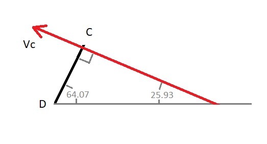
$v_C=ϖ_{CD}~×~r_C$
$v_C=ϖ_{CD}~×~(2cos(64.07)i+2sin(64.07)j)$
$v_C=ϖ_{CD}~×~(0.87i+1.80j)$
$v_C=-1.80ϖ_{CD}i+0.87ϖ_{CD}j$
or
$v_{C_i}=-1.80ϖ_{CD}$
$v_{C_j}=0.87ϖ_{CD}$
Step 4: Now you can combine the equations in step 2 and 3 to find $ϖ_{CD}$ and $ϖ_{BC},
$-1.80ϖ_{CD}=-16-ϖ_{BC}$
$0.87ϖ_{CD}=19.2+5.91ϖ_{BC}$
$ϖ_{BC}=-2.12\frac{rad}{s}$
$ϖ_{CD}=7.7\frac{rad}{s}$
$v_C=-13.9i+6.70j=15.4\frac{in}{s}$
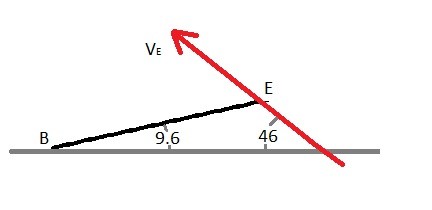
Step 5: Because the angular velocity of link BC is known we can now find the velocity at point E by using equation 3.
$v_E=v_B+ϖ_{BC}~×~r_{E/B}$
$v_E = -16i+19.2j-2.12k~×~(1.48i+0.25j)$
$v_E = -15.47i+16.06j=22.3\frac{in}{s}$
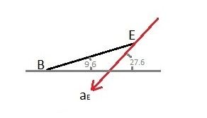
You can also use instantaneous center of zero velocity to the find the angular velocity of link BC and the velocity of point C when the velocity at point B is known. The reason why is because links AB’s and CD’s motion is rotation about a fixed axis which means the velocity at point B and C will always be perpendicular to the link. In turn, this will allow you to use this method before knowing what the velocity is at one of the two points.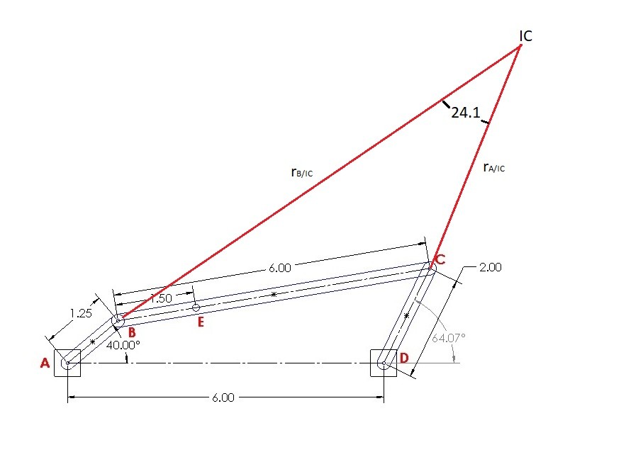
To determine the imaginary lines $r_{B/IC}$ and $$r_{C/IC}$ you will need to use the law of sines.
$r_{B/IC}=sin(115.9)\frac{6}{sin(24.1)}-1.25=11.98~in$
$r_{C/IC}=sin(40)\frac{6}{sin(24.1)}-2=7.45~in$
Finally, equation 4 will be used find angular velocity of link BC and the velocity at C.
$ϖ_{BC}=\frac{-25}{11.98}= -2.09\frac{rad}{s}$
$v_C=7.45\left(\frac{25}{11.98}\right)= 15.5\frac{in}{s}$
The slight difference between the results is due to round off error.
Acceleration
Next, to find the relative acceleration of a rigid body that is under general plan motion you will need to find the derivative of the velocity equation in respect to time.
$\frac{dv_B}{dt} =\frac{dv_A}{dt}+\frac{dv_{B/A}}{dt}$
Eq 5 $a_B=a_A + (a_{B/A})_t+(a_{B/A})_n$
Notice that there is a relative tangential acceleration and a normal acceleration in equation 5. Because of this we will need to know the angular velocity and angular acceleration that is acting on the rigid body to find how the accelerations at point A and B relate to each other.
Eq 6 $a_B=a_A+α~×~r_{B/A}-ϖ^2r_{B/A}$
where
$a_B$ = acceleration at point B
$a_A$ = acceleration at point A
$α$ = angular acceleration of the body
$ϖ$ = angular velocity of the body
$r_{B/A}$ = relative-position vector from point A to point B
Example
Let’s revisit the linkage problem in the first and second example. For position 1 the angular velocity ϖ of link AB will remain at a constant velocity of 20 rad/s. Determine the acceleration at at points B,C and E as well as the angular acceleration of link BC and link CD. All dimensions are in inches.
Solution
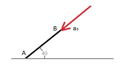
Step 1: Determine the acceleration at point B.
$a_B=-ϖ_{AB}^2r_B$
$a_B=-(20^2)(0.96i+0.80j)$
$a_B = -384i-320j = 500\frac{in}{s^2}$
Step 2: Find the acceleration at point C and the angular acceleration of BC using equation 6.
$a_C=a_B+α_{BC}~×~r_{C/B}-ϖ_{BC}^2r_{C/B}$
$a_C=-384i-320j+α_{BC}~×~(5.91i+1j)-(2.12^2)(5.91i+1j)$
$a_C=(-410-α_{BC})i+(-324.5+5.91α_{BC})j$
$a_{C_i} = -410-α_{BC}$
$a_{C_j} = -324.5+5.91α_{BC}$
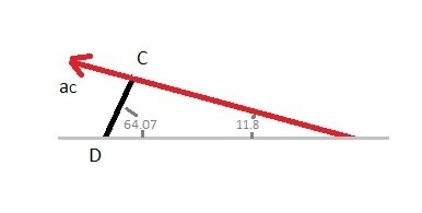
Step 3: Currently there are to many unknowns to solve for in the equations above. However, deriving the equation of acceleration for link CD will also allow you to find the acceleration at point C.
$a_C=α_{CD}~×~r_{C}-ϖ_{CD}^2r_{C}$
$a_C=α_{CD}~×~(0.87i+1.80j)-(7.7^2)(0.87i+1.80j)$
$a_C=-1.80α_{CD}i+0.87α_{CD}j-51.6i-106.7j$
$a_{C_i}=-1.80α_{CD}-51.6$
$a_{C_j}=0.87α_{CD}-106.7$
Step 4: You can now combine the equations in step 2 and 3 and solve for α_{BC} and α_{CD}.
$-1.80α_{CD}-51.6=-410-α_{BC}$
$0.87α_{CD}-106.7=-324.5+5.91α_{BC}$
$α_{BC}=72\frac{rad}{s^2}$
$α_{CD}=239\frac{rad}{s^2}$
$a_C=-481.8i+101j =492 \frac{in}{s^2}$
Step 5: Finally, you can now determine the acceleration at point E by using equation 6.
$a_E=a_B+α_{BC}~×~r_{E/B}-ϖ_{BC}^2r_{E/B}$
$a_E=-384i-320j+72~×~(1.48i+0.25j)-(2.12^2)(1.48i+0.25j)$
$a_E = -409i-214j = 462\frac{in}{s^2}$