As an object moves through a fluid a net force around that object will be generated. If that object is symmetrical parallel to the upstream flow a drag force will result. However, if the object is not symmetrical a force that is normal to the free stream will result. This force is called lift.
Pressure Distribution
If you know the pressure distribution of the fluid on the surface of the object of interest than you will be able to determine the lift. However, this is normally not known. Nor is it easy to calculate analytically. Instead a lift coefficient is used.
(Eq 1) $C_L = \frac{L}{\frac{1}{2}ρU^2A}$
$C_L$ = Lift Coefficient
$L$ = Lift
$ρ$ = Fluid Density
$U$ = Fluid Velocity
$A$ = Frontal Area
To determine the lift coefficient, experiments can be conducted, advanced analysis can be done, or numerical considerations can be used. In addition, like the drag coefficient, the lift coefficient is a function of the following dimensionless parameters.
(Eq 2) $C_L = Φ(Shape,~ Re,~Ma,~Fr,~ε/l)$
In the above expression, $Re$ represents the Reynolds number, $Ma$ represents the Mach Number, $Fr$ represents the Froude Number, and $ε/l$ represents the surface roughness per unit length. Generally, Froude number is only considered when a free surface is present. This occurs when analyzing an underwater wing, such as what is used to support a hydrofoil surface ship. In addition, Mach number effects are more prominent for high speed subsonic speeds and super sonic speeds. Out of all of the parameters in the expression above, the shape of the object has the most influence on lift. Because of this considerable effort goes into designing the optimal shape for lift producing objects.
Similar to drag, for high Reynolds numbers pressure has more of an influence than viscous forces. As a result, most of the lift will occur from surface pressure distribution. On the other hand flows that have a low Reynolds number, $Re<1$, viscous forces due to shear stress will have much more of an influence and can be just as important as pressure.
Airfoils
An airfoil is device that is specifically designed to produce lift. It does this by creating a pressure difference between the top surface of the airfoil and the bottom surface. In addition, the pressure distributions on an airfoil is directly proportional to the dynamic pressure $ρU^2/2$ for large Reynolds number flows.
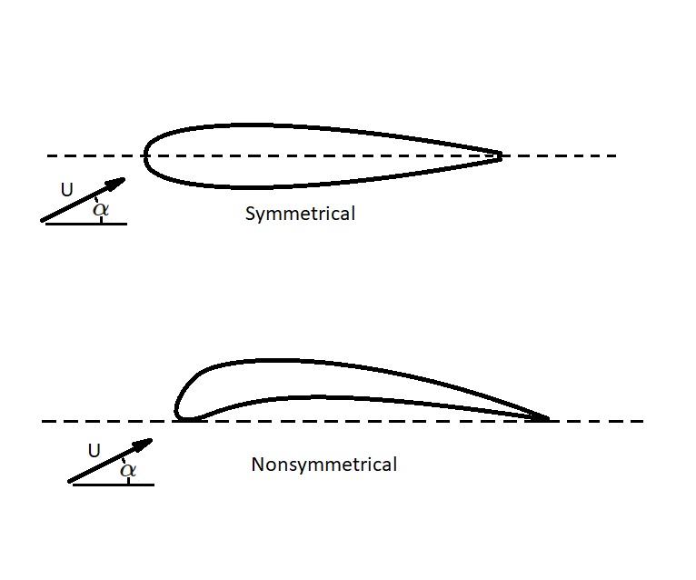
There are two basic type of airfoils. They are symmetrical and non-symmetrical airfoils. As mentioned above, for an airfoil to produce lift there must be pressure difference between the top and bottom of the airfoil. For this to occur on a symmetrical airfoil, the angle of attack, α, must be non-zero. The angle of attack is the angle of the airfoil in respect to the direction of the airflow. For a non-symmetrical airfoil the pressure difference between the top and bottom is a function of shape. As a result, the angle of attack for a non-symmetrical airfoil can be zero and still produce lift. The image below shows the difference between a symmetrical and non-symmetrical airfoil.
To calculate the lift on an airfoil you will need to know what the planform area is. However, since most airfoils are thin the planform area can be calculated using the following equation.
(Eq 3) $A=bc$
$b$ = length of airfoil
$c$ = chord length
Taking in consideration that lift force can be defined as a product of dynamic pressure and planform area, the following equation can be used.
(Eq 4) $L=(ρU^2/2)A$
Finally, another thing that you may need to consider is wing loading. Wing loading is the average lift per unit area of the wing, $L/A$. As the speed of the fluid moving over the wing increases, the wing loading will also increase.
Angle of Attack and Aspect Ratio
Both the lift and drag coefficients are a function of angle of attack, $α$, as well as the aspect ratio, $À$. The angle of attack is the angle that a fluid is moving over the airfoil. In addition, the aspect ratio is the ratio of the square of wing length to the planform area.
(Eq 5) $À=b^2/A$
Normally, as the lift coefficient increases, the drag coefficient will decrease. In addition, the aspect ratio will increase. Refer to the figure below.
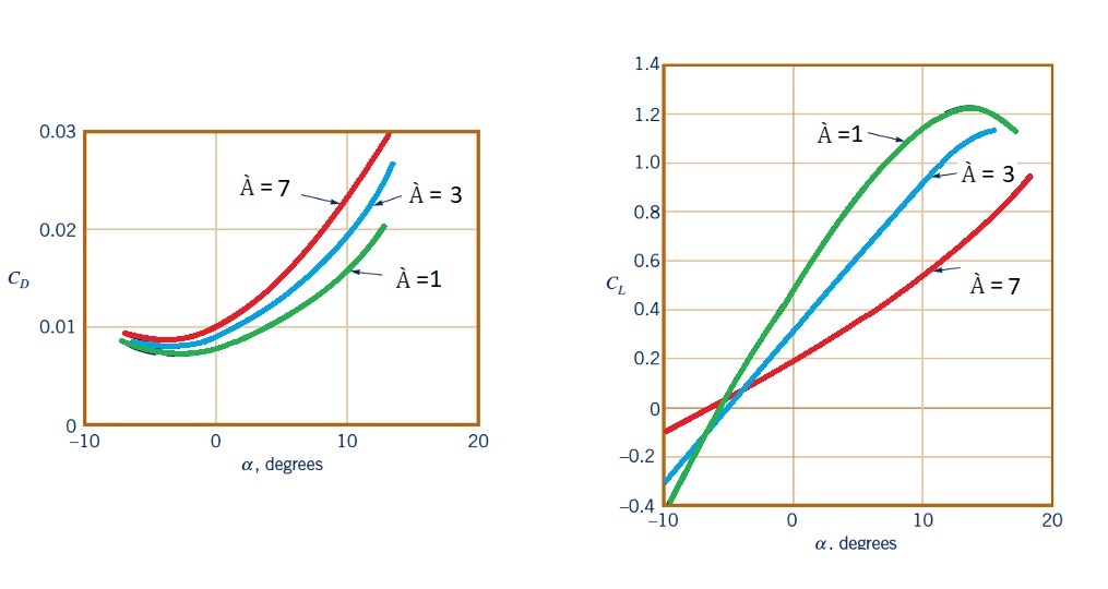
When you are looking at wing length, long wings will be more efficient than short wings. This is because the losses at the wing tips have less of an influence for longer wings than shorter wings. The loss at the wing tips is due to a complex swirling flow structure. Finally, even though longer wings are more efficient, due to their large inertia, rapid maneuvers cannot be accomplished. Instead for planes that need to perform rapid maneuvers, like a fighter jet, the wings will need to have a small aspect ratio.
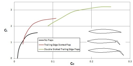
Stall
On an object viscous effects have very little effect on generating lift. However, they do still need to considered. This is because, depending on the angle of attack, a viscosity induced boundary layer separation can occur. In turn, this will cause drag to increase and lift to decrease due the development of a large turbulent wake region. Eventually, this will lead to stall, which is when the airfoil can no longer produce enough lift to over come drag caused by the boundary layer separation.
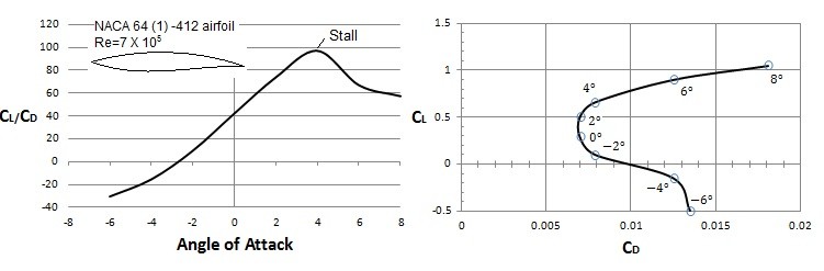
The image above shows that the lift and drag coefficients will change depending on the angle of attack. This is because you are in a way changing the shape that the fluid flows over. In addition, in order to purposely change the shape, flaps on airplane wings are used to change the lift and drag coefficients. For example, when landing and taking off a plane will extend its flaps into the “dirty” configuration. This will increase lift while also increasing drag. The increase in drag during landing and take off however isn’t much of a concern. However, once a plane reaches cruising speeds and altitudes, to much drag will waste fuel. Hence, the plane will retract the wing flaps to reduce drag.