As fluid moves through a pipe it will experience losses. These losses are the major and minor head loss. In a previous article I discussed major head loss, which is the pressure drop caused by the fluids friction in relation to the length of pipe. However, most piping systems have bends, changes in cross-sectional area, and valves. All of these can also cause a loss. This loss is called the minor head loss. The total head loss is found by adding the major and minor head losses together.
$h_L=h_{L~major}+h_{L~minor}$
Minor Head Loss
A minor head loss, despite its name, can be a greater loss than the major head loss, depending on the situation. For example, the flow through a valve will cause a minor head loss. This loss, however, is actually something that can be changed by an operator. As the operator closes the valve, the loss will increase, reducing the flow of the fluid to a point where the fluid will stop flowing. On the other hand, when the operator opens the valve the loss will decrease, allowing the fluid to flow more freely. This loss is based off of the geometry inside the valve, and as the geometry is manipulated by opening and closing the valve, so isn’t the loss.
It is easy to understand why a minor head loss would occur. However, a theoretical method has not yet been developed to solve for a minor head loss mathematically. Instead experimental data has to be used to determine the loss coefficient $K_L$. Once the loss coefficient is known than pressure drop can be determined.
$K_L=\frac{h_{L~minor}}{v^2/2g}=\frac{Δp}{\frac{1}{2}ρv^2}$
so that
$Δp=K_L\frac{1}{2}ρv^2$
or
(Eq 1) $h_{L~minor}=K_L\frac{v^2}{2g}$
$v$ = fluid velocity
$ρ$ = fluid densisty
$g$ = gravitational constant ($9.81~m/s^2$ or $32.2~ft/s^2$
Loss Coefficient $K_L$
This means that if $K_L=1$ than it will be equal to the dynamic pressure $ρv^2/2$. In other words, $K_L$ is proportional to the square of the fluid velocity. In addition, as mentioned above, $K_L$ is highly dependent geometry of the object that the fluid is flowing through. Thus, through dimensional analysis, the following statement for the loss coefficient is true.
(Eq 2) $K_L=Φ(geometry,~Re)$
where
$Re=\frac{ρvD}{μ}$
$D$ = pipe diameter
$μ$ = Dynamic Viscosity
Generally, the Reynolds number, $Re$, is significantly large enough that inertial effects dominate the flow. As a result, the viscous effects of the flow are no considered important when determining the loss coefficient. The reason for this is because the sudden change in flow direction can cause large accelerations and deceleration within the fluid flow. As a result, the minor head losses and associated pressure drop will correlate with the dynamic pressure. Hence, the friction factor for very large Reynolds numbers will actually be independent of the Reynolds number. In turn the mathematical expression in equation 2 can b simplified to the following.
(Eq 3) $K_L=Φ(geometry)$
Equivalent Length
Occasionally minor head loss is give in terms of equivalent length, $l_{eq}$. Equivalent length is a theoretical length of pipe that would produce the same head loss as the component. Hence,
(Eq 3) $h_{L~minor}=K_L\frac{v^2}{2g}=f\frac{l_{eq}}{D}\frac{v^2}{2g}$
$f$=friction factor
or
(Eq 4) $l_{eq}=\frac{K_LD}{f}$
Both $D$ and $f$ are based off of the pipe that is containing the component of interest. As a result, by taking this approach, the total head loss of the system will be based off the actual pipe length with the equivalent pipe length added on.
Minor Head Loss: Change in Pipe Diameter
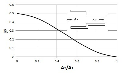
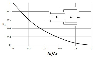
In a system of pipe there are various types of transitions that can occur. One type transition is when the pipe diameter changes. Any change in the pipe diameter will cause a loss that is not accounted for with major head loss. The graphs below can be used to determine the loss coefficient for a sudden change in pipe diameter.
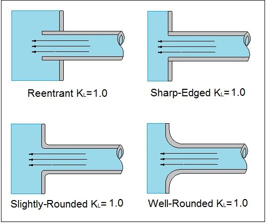
In addition, there could be an extreme change such as when a fluid enters or exits a reservoir. The images below provide the loss coefficient for this type of situation.
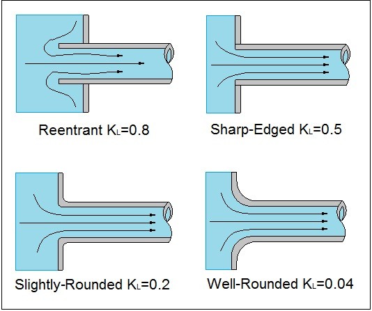
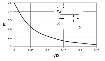
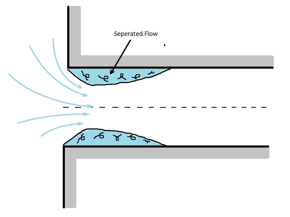
In the images above we see a fluid entering a pipe from a reservoir. The losses occur because a fluid cannot effectively turn a right angled corner. How large the loss is, is dependent on how sharp the corner is. As a result, the more rounded the corner, the less loss will occur. The reason why a loss occurs is because the fluid will separate from the sharp corner as seen in the image below.
In addition to a flow entering a pipe from a reservoir, it can exit a pipe into a reservoir. When this is the case the kinetic energy of the fluid will completely dissipate as it enters the reservoir.
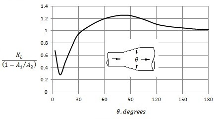
Conical Diffuser
By gradually changing the diameter, the losses can be minimized. To do this a conical diffuser would be used. For a conical diffuser, the angle $θ$ is a very important parameter. For an angle that is very small, most of the loss will be due to friction instead of the change in diameter. However is this will result in a long diffuser that is not practical. On the other hand, a diffuser with steep angle will cause flow separation causing a loss of kinetic energy. Generally, the angle of the diffuser must be less than $35^o$ for it to be efficient. The graph below can be used to find the loss coefficient of a diffuser.
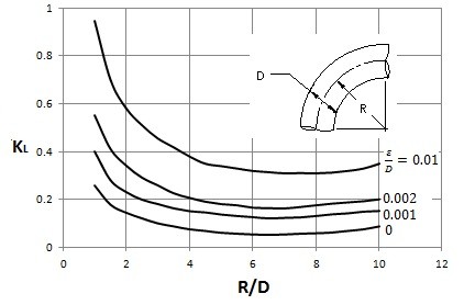
Minor Head Loss: Bends
Bends allow a change in direction of the flow. However, this will also cause a loss due to separated region of flow near the inside of the bend. This separation region will be more pronounced the sharper the bend is. To determine the loss coefficient of a $90^o$ bend, the following graph can be used.
Various Loss Coefficients
Elbows
- Regular $90^o$, flanged ($K_L = 0.3$)
- Regular $90^o$, Threaded ($K_L =1.5$)
- Long Radius $90^o$, flanged ($K_L=0.2$)
- Long Radius $90^o$, threaded ($K_L=0.7$)
- Long Radius $45^o$, flanged ($K_L=0.2$)
- Regular $45^o$, threaded ($K_L=0.4$)
$180^o$ Return Bends
- Flanged ($K_L=0.2$)
- Threaded ($K_L=1.5$)
Tees
- Line Flow, Flanged ($K_L=0.2$)
- Line Flow, Threaded ($K_L=0.9$)
- Branch Flow, Flanged ($K_L=1.0$)
- Branch Flow, Threaded ($K_L=2.0$)
Valves
- Globe, fully open ($K_L=10$)
- Angle, fully open ($K_L=2$)
- Gate, fully open ($K_L=0.15$)
- Gate, 1/4 closed ($K_L=0.26$)
- Gate, 1/2 closed ($K_L=2.1$)
- Gate, 3/4 closed ($K_L=17$)
- Swing Check, Forward Flow ($K_L=2$)
- Swing Check, Backward Flow ($K_L=∞$)
- Ball valve, fully open ($K_L=0.05$)
- Ball valve, 1/3 closed ($K_L=5.5$)
- Ball valve, 2/3 closed ($K_L=210$)