A pressure drop, also known as a head loss, will occur as a fluid moves through a pipe. There are two types of head loss that need to be considered. They are major head loss and minor head loss. However, for this article I will be focusing on major head loss.
Major Head Loss: Dimensional Analysis
The major head loss inside a pipe is dependent on the wall shear stress, $τ_w$, between the fluid and the pipe’s surface. As a result, tt will occur for both laminar and turbulent flow situations. However, for turbulent flow the shear stress is dependent on fluid density, $ρ$. On the other hand, for laminar flow shear stress is independent of fluid density making it only dependent on fluid viscosity, $μ$.
In order to determine the pressure drop caused by a major head loss a dimensional analysis can be performed. After gathering all of the necessary variables, the functional form will be the following.
(Eq 1) $Δp=F(v,~D,~l,~ε,~μ,~ρ)$
where
$v$ = average velocity
$D$ = pipe diameter
$l$ = pipe length
$ε$ = surface roughness of the pipe wall
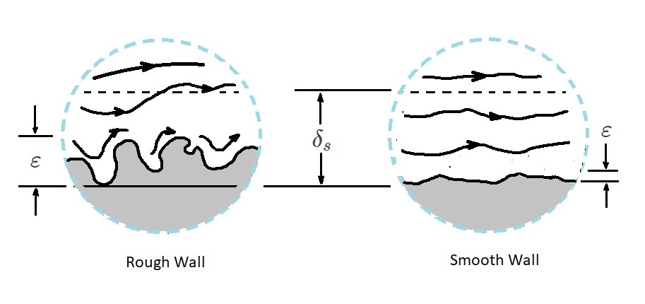
For the above expression, if the flow is laminar, the surface roughness of the pipe wall does not need to be considered. However, for turbulent flow, the surface roughness is an important factor. This is because of a thin viscous sub layer that forms at the pipe’s wall. The sub layer is normally extremely thin; $δ_s/D<<1$ where $δ_s$ is the sub layer thickness. It is so thin that it is possible that a very small surface imperfection could protrude significantly far into or through this sub layer causing the surface of the pipe to influence the flow of this sub layer. For a laminar flow this sub layer is not present which is why surface roughness in unimportant. The image below shows how surface roughness can influence the viscous sub layer of a turbulent flow.
The surface roughness range that will be focused on will be between $0≤ε/D≤0.05$. This is because the flow will become a function of the surface roughness for surface roughness that are $ε/D≥0.1$. Pipes that have a large surface roughness compared to the diameter generally do not fit into the constant diameter pipe diameter which is why they are not be considered.
To continue the dimensional analysis, we need to note that there are seven variable in equation 1. Due to this fact $k=7$. In turn, their are three reference dimensions, $MLT$, or $r=3$. As a result, $k-r=4$. This will allow us to write the seven variables into dimensionless groups.
(Eq 2) $\frac{Δp}{\frac{1}{2}ρv^2}=Φ\left(\frac{ρvD}{μ},~\frac{l}{D},~\frac{ε}{D}\right)$
where
$Re=\frac{ρvD}{μ}$
The above equation is for turbulent flow. Recall that for laminar flow that surface roughness does not need to be considered. As a result, $ε/D$ does not need to be included in the dimensionless group. In addition, for turbulent flow we are currently dividing by the dynamic pressure, $ρv^2/2$. However, for laminar flow we want to use the characteristic viscous shear stress, $μv/D$, since laminar flow is not dominated by $τ_{turb}$. This is because the density $ρ$ is not a driving parameter for laminar flow.
Taking this into consideration the dimensionless group can be simplified by making the assumption that pressure drop should be proportional to pipe length. By making this assumption $l/D$ can be factored out of the dimensionless group in the following way.
(Eq 3) $\frac{Δp}{\frac{1}{2}ρv^2}=\frac{l}{D}Φ\left(Re,~\frac{ε}{D}\right)$
or
(Eq 4) $Δp=f\frac{l}{D}\frac{ρv^2}{2}=h_{L~major}$
where
$f=Φ\left(Re,~\frac{ε}{D}\right)$
If the flow is laminar $f$ will simply become,
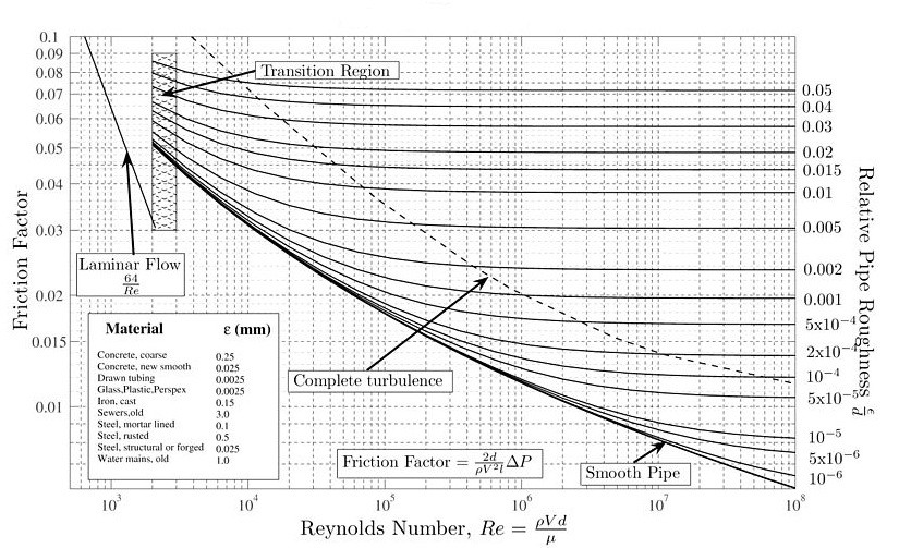
$f=\frac{64}{Re}$ (laminar flow)
However, if the flow is turbulent, than the Moody chart is used to determine what $f$ is.
Finally, the following table can be used to determine the typical surface roughness $ε$ for various pipe materials.
|
Equivalent Roughness, ε |
||
| Pipe | Feet | Millimeters |
| Riveted Steel | 0.003-0.03 | 0.9-9.0 |
| Concrete | 0.001-0.01 | 0.3-3.0 |
| Wood Stave | 0.0006-0.003 | 0.18-0.9 |
| Cast Iron | 0.00085 | 0.26 |
| Galvanized Iron | 0.0005 | 0.15 |
| Commercial Steel | 0.0005 | 0.15 |
| Wrought Iron | 0.00015 | 0.045 |
| Drawn Tubing | 0.000005 | 0.0015 |
| Plastic, Glass | 0.0 (smooth) | 0.0 (smooth) |