Cyclic devices are more efficient when using reversible processes. One of the best known reversible cycles is called the Carnot cycle. The Carnot cycle is made of four reversible processes. They are two isothermal processes and two adiabatic processes. Finally, a Carnot cycle can be executed for a closed system as well as a steady-flow system.
Carnot Cycle: Closed System
The image below represents an adiabatic piston cylinder device. As this cylinder goes through its cycle it will move through the four reversible processes of the Carnot cycle.
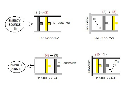
Reversible Isothermal Expansion
First, process 1-2 represents reversible isothermal expansion. As a result, $T_H$ = constant. In turn, the temperature of the gas inside the cylinder will be at $T_H$. In addition, the cylinder head will be in contact with a source at $T_H$. Next, the gas will be allowed to expand slowly doing work on its surroundings.
Note, that as the gas expands its temperature will drop. However, because the gas expansion is occurring slowly, the source $T_H$ will transfer heat back into the the cylinder keeping the gas temperature relatively constant. In turn, the gas temperature will never exceed a differential amount dT, allowing a reversible heat transfer process to occur.
Finally, the total heat transferred to the gas during this process represents $Q_H$.
Reversible Adiabatic Expansion
During process 2-3 the temperature will drop from $T_H$ to $T_L$. However, in order for this to be an adiabatic process, the thermal reservoir that was contacting the cylinder head will be replaced with a thermal insulator. In turn, this will prevent heat from transferring from the surrounding environment, making this an adiabatic process. Finally, while the temperature drops from $T_H$ to $T_L$, the gas inside the piston will continue to expand which will continue to do work on the surroundings. The piston is assumed to be frictionless and the process is quasi-equilibrium.
Reversible Isothermal Compression
Next, process 3-4 is a reversible isothermal compression process. During this process $T_L$ = constant. In addition, at state 3 the insulator at the cylinder head will be replaced with a sink that is at temperature $T_L$. Next, an external force will be placed on the piston to slowly push it inward. Naturally, as the gas is compressed, the temperature will start to rise. However, as it rises the infinitesimal amount of $dT$ will be transferred into the sink. In turn, this will keep the gas temperature constant. As a result, the temperature difference between the sink and gas will never exceed a differential amount dT, allowing this process to be a reversible heat transfer process.
$Q_L$ represents the amount of heat rejected from the gas.
Reversible Adiabatic Compression
Finally, the last process 4-1 is a reversible adiabatic compression. At state 4 the low temperature sink is replaced with the insulator to prevent heat transferring to the environment. Next, the piston will continue to compress the gas causing the temperature of the gas to rise from $T_L$ to $T_H$ returning it to its initial state.
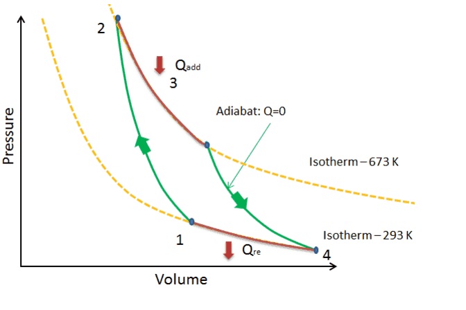
The P-ν diagram below represents the Carnot cycle.
Carnot Principles
Due to the Kelvin-Planck and Clausius statements, which express the second law of thermodynamics, there are limits on the operation of cyclic devices. As a result, heat engines can only operate when there are two reservoirs, a source and sink. In addition, refrigerators must have a net energy input from an external source to operate.
Taking in consideration of the Kelvin-Planck and Clausius statements, the Carnot principles are derived.
“The efficiency of an irreversible heat engine is always less than the efficiency of a reversible one operating between the same two reservoirs.”
“The efficiencies of all reversible heat engines operating between the same two reservoirs are the same.”
Carnot Heat Engine
A Carnot heat engine is a hypothetical heat engine that operates on the reversible Carnot cycle. The efficiency of this heat engine is determine by the following equation.
(Eq 1) $η_{th}=1-\frac{Q_L}{Q_H}$
In the above equation, $Q_H$ is the amount of heat transferred to the heat engine for the high-temperature reservoir $T_H$. On the other hand, $Q_L$ is the amount of heat rejected to the low temperature reservoir $T_L$.
Due to the fact that this is a reversible heat engine, the heat transfer ratio in equation 1 can be replaced with the ratio of the absolute temperatures of the two reservoirs. Refer to the equation below.
(Eq 2)$η_{th}=1-\frac{T_L}{T_H}$
This relationship is is referred to as the Carnot efficiency.
The Carnot heat engine is the best known reversible heat engine. This means that it is impossible for a heat engine to have better efficiency than a Carnot heat engine. As a result, the following statement for all heat engines would apply.
irreversible heat engine: $η_{th}<η_{th,rev}$
reversible heat engine: $η_{th}=η_{th,rev}$
impossible heat engine: $η_{th}>η_{th,rev}$
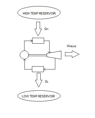
The diagram below represents a Carnot heat engine.
Generally, most heat engines will operate at efficiencies lower than 40 %. Even though this may seem low, the efficiency of the heat engine shouldn’t be compared to 100%, instead it should be compared to the reversible heat engine operating between the same temperature limits. For example, if the temperature limits were 293 K and 700 K, the maximum efficiency this heat engine could achieve would be 58%. This maximum efficiency can be increased by decreasing $T_L$ or increasing $T_H$.
Carnot Refrigerator and Heat Pump
Next, a Carnot Refrigerator is a hypothetical Refrigerator operating on the reversed Carnot cycle. The equation below is used to determine its coefficient of performance.
(Eq 3) $COP_R=\frac{1}{Q_H/Q_L-1}$
As with the heat engine, the absolute temperature ratio of the two reservoirs can replace the heat transfer ratio to calculate its coefficient of performance.
(Eq 4) $COP_{R,rev}=\frac{1}{T_H/T_L-1}$
In addition, the Carnot cycle can also be used to represent a heat pump, which is known as the Carnot heat pump. The following equation is used to determine its respective coefficient of performance.
(Eq 5) $COP_{HP}=\frac{1}{1-Q_L/Q_H}$
or
(Eq 6) $COP_{HP,rev}=\frac{1}{1-T_L/T_H}$
The resulting coefficient of performance for both the Carnot refrigerator and Carnot heat pump represent the highest possible COP between the temperature limits $T_L$ and $T_H. In reality, any actual heat pump or refrigerator will have a lower coefficient of performance. As a result, the following statement will hold true for an actual and a reversible refrigerator operating between the same temperature range.
irreversible refrigerator: $COP_{R}<COP_{R,rev}$
reversible refrigerator: $COP_{R}=COP_{R,rev}$
impossible refrigerator: $COP_{R}>COP_{R,rev}$
For both heat pumps and refrigerators, the coefficient of performance will decrease as $T_L$ decreases. This is because more work is required to absorb heat from the low temperature environment.