Article Content Links: Shaft Materials, Shaft Layout, Torque Transmission, Calculating Static Stresses, Dynamic Stresses and Fatigue, Determining Critical Stress Locations, Deflection, Critical Speed
A shaft is a mechanical part that normally has a circular cross-section. It is used to transmit power through rotation. It provides an axis of rotation for a variety of mechanical components fastened to it such as, sprockets, gears, pulleys, flywheels, and cams. Finally, it is used to control the geometry of their motion while they are rotating.
A shaft is not to be confused with an axle, which is actually by definition a nonrotating member that carries no torque, and is instead used to support wheels and other rotating object. An automobile axle is not a true axle but instead by definition is a shaft. When analyzing a true axle you would only have to look at it is a static beam and perform a static analysis on it. A shaft on the other hand will also need to have a dynamic analysis performed on it to determine fatigue stress.
Shaft Materials
Article Content Links: Shaft Materials, Shaft Layout, Torque Transmission, Calculating Static Stresses, Dynamic Stresses and Fatigue, Determining Critical Stress Locations, Deflection, Critical Speed
Generally, for most applications, steel is the most popular choice of material for shafts. However, aluminum could be used, as well as exotic materials such as titanium. For this article I am going to mainly discuss steel.
There are two main criteria’s of interest that need to be considered when selecting a material. These are strength and stiffness. Stiffness is related to the Young’s Modulus of the material, while strength is based off the yield strength and ultimate strength of the chosen material.
First, let’s talk about stiffness. As mentioned above, stiffness is a function of the materials Young’s modules. Now, for most steels, the Young’s Modulus is essentially constant. This means the rigidity of the shaft, if steel is the chosen material, is not dependent on the Young’s modulus, but is instead dependent of the shafts geometry.
Most of the loads on a shaft will be perpendicular to the shafts axis. This means beam analysis will need to be used to calculate the total deflection the shaft. However, there could be cases where there will also be axial forces on the shaft. For example if thrust bearing is used. Finally, most shafts will have torsional aspect that will need to be looked at, since they are used to transfer torque from one component to another.
Different grades of steel, however, does effect the yield strength and the ultimate strength of the material. Many shafts in most applications are made from low carbon, cold drawn, or hot – rolled steel. The reason for this is because strengthening the steel by heat treating or using a high alloy steel generally isn’t warranted, and only moderately reduces the fatigue failure of the shaft. Instead it is best to start a design with an inexpensive steel when you first start laying out you design and then determine later if you need to change it to a different material.
As mentioned above you can also choose to heat treat the steel to increase its strength. Some steels that can be heat treated are the following. ANSI 1340-50, 3140-50, 4140, 4340, 5140, and 8650.
There also may be cases when you need to surface hardened the shaft. An example might be if the shaft is also the journal for a bearing. In these cases you could use the following materials ANSI 1020, 4320, 4820, and 8620.
If you choose to use a cold drawn steel. You will normally need to keep the largest diameter of the shaft under 3 inches. While if you choose to use hot rolled steel all of it surfaces will need to be machined so that it runs true. Finally, for shafts that are large, and that require a large quantity of material to be removed by machining, residual stresses that will build up during the machining process could cause it to warp. It is best practice to rough cut the part first, heat treat it to remove the residual stresses, than perform a finish cut on the part to reach the desired dimensions.
It is also best practice to design a shaft that will use the least amount material, but is also close to stock dimensions so that only a little material needs to be removed during the machining process. This is for economical reason.
Finally, there may also be cases, where you will need to choose stainless steel instead of a carbon steel. These cases are normally due to environmental factors, such as an environment that has a high salt content.
Shaft Layout
Article Content Links: Shaft Materials, Shaft Layout, Torque Transmission, Calculating Static Stresses, Dynamic Stresses and Fatigue, Determining Critical Stress Locations, Deflection, Critical Speed
At the very beginning of your design you need to determine the layout on the shaft. You need to decide where all of the gears, bearing, pulleys, etc will be make contact with the shaft. Than you need to determine what type of load the object will put on the shaft. After doing this you can generate a free body diagram to see how forces will interact, which will than allow you to determine where the maximum stress and displacement will occur. It will also allow you to create a shear and moment diagram, which can then be used to determine the shear stresses and bending stresses at any point on the beam.
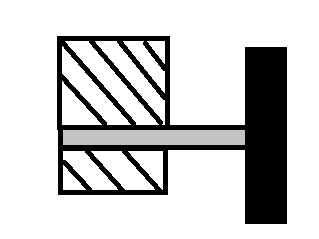
Typically, the geometry of a shaft is a stepped cylinder. This will help position components. It will also help support components when there is an axial force due to a thrust load. An example of a component that would produce a thrust load is a worm gear. The steps on a shaft will only hold the component on one side. If both sides need to be supported than a retaining ring, a spacer, or clamp will need to be added to hold the component on both sides. By having the component firmly support not only does this help with alignment, it also can help reduce vibration and chatter from the component while it is in operation. Below is an example of a stepped cylinder shaft.
It is best practice to support load carrying components between bearings, instead of having them cantilevered. However, for ease of assembly sometimes components may need to be cantilevered, such as sprockets and pulleys. This will allow for easier assembly of the chain or the belt. When you cantilever a component, it is best to keep the cantilever as short as possible to help minimize deflection.
Most shafts also will only need to have two bearings supporting it, with one bearing on each end of the shaft. However, for extremely long shafts that is carry several load bearing components, additional bearings may need to be added in key areas to minimize bending moments and deflection.
There will also be cases where axial loading isn’t trivial. As mentioned above, one case would be when a worm gear is placed on the shaft. When this is the case, you will need to provide a path for the axial load to transfer through bearing into ground. You can do this by using a retaining ring, a shoulder on the shaft, or pins to hold the component in place, so that the axial load is transmitted into the shaft. The bearing that has the axial load transmitting into it will need to be a thrust bearing. The bearing will also need to have a shoulder behind it to support so it doesn’t move.
Finally, remember during design, it is always important to think about how you would assemble and disassemble the components onto and off of the shaft. Generally, components that are assembled onto the center of the shaft have larger hub diameters which will become progressively smaller towards the end of the shaft. As mentioned above, if you require a shoulder on each side of the component you will need to use some sort of a retaining ring or clamp. Finally, if you are using press fitted components, you will need to pay attention to your tolerances. You will also need to think about how you are going to press the components on during assembly, and how you would pull the components off if you ever had to disassemble the assembly.
Torque Transmission
Article Content Links: Shaft Materials, Shaft Layout, Torque Transmission, Calculating Static Stresses, Dynamic Stresses and Fatigue, Determining Critical Stress Locations, Deflection, Critical Speed
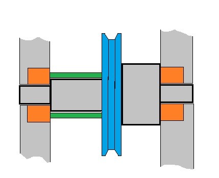
In addition to laying out the components you will also need to design a torque transfer feature on the shaft and the components that mount onto the shaft. Some of examples are keyways, set screws, spines, pins, or a press fit. When designing these elements, you might want to design these elements so that they will fail if the torque exceeds a critical value. This will help protect critical components. Refer to the image below to see the difference between splines, keyways, pins, and set screws.
![]()
Splines are similar to keys except instead of having one point of transmission into the shaft, there are multiple points where the torque can be transmitted into the shaft. Splines are essentially stubby gear teeth formed on the outside of the shaft and on the inside of the component. Splines can be much more expensive to manufacture than keys would be, and generally are not necessary for simple torque transmission. They are generally on needed for high torque applications.
Finally, if you only need to transmit low torque, than pins, set screws, or pressed fits could be used. All three of these cases would provide a point of failure if torque levels become too high. Pins however, are the better component to use if you want a failure to occur if you expect there is a change that torque levels could become too high. The reason why is because set screws and press fits can mar up the surface of the shaft, causing issues later when you try to fix the assembly.
Calculating Static Stresses
Article Content Links: Shaft Materials, Shaft Layout, Torque Transmission, Calculating Static Stresses, Dynamic Stresses and Fatigue, Determining Critical Stress Locations, Deflection, Critical Speed
Let’s look at a simple example. Let’s say that the wheel shown in the image below is supporting an object that weighs 500lb and 25 ft-lb is be transmitted through the shaft to the wheel in order to move the object that the wheel is supporting.
To calculate a stress due to a moment caused by bending the following equation would be used. Note the stress due to a moment is a normal stress.
(Eq 1) $σ=\frac{Mc}{I}$
$M$ = Moment
$C$ = distance to the neutral axis
$I$ = Area Moment of Inertia
To calculate the shear stress due to bending, also known as transverse shear, the following equation would be used.
(Eq 2) $τ=\frac{VQ}{IW}$
$V$ = Shear Force
$I$ = Area moment of inertia
$w$ = width of cross-sectional area.
(Eq 3) $Q=y’A’$
Q represents the area above the point of interest in relation to that area’s centroid, and the main cross-section’s centroid.
![]()
(Eq 4) $τ_{max}=\frac{Tr_o}{J}$
$T$ = Torque
$r_o$ = Outer Radius
$J$ = Polar Moment of Inertia
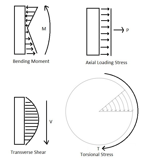
Notice for the above example there are 3 different stresses that can be determined. There is a normal stress due to bending, there’s a transverse shear stress due to bending, and there is a shear stress due to torsion. There can also be fourth stress that wasn’t shown in the example. This a normal stress due to an axial force. Refer to the image below.
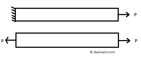
(Eq 5) $σ=\frac{F}{A}$
$F$ = Axial Load
$A$ = Cross-Sectional Area
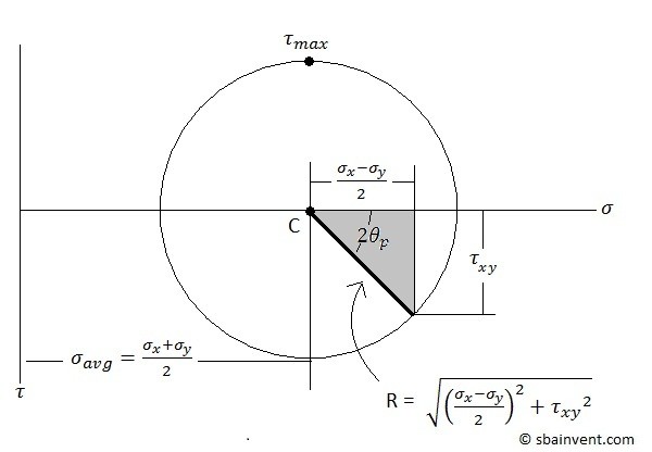
Now that all four different types of stress have been discussed the next step is to find the maximum normal and maximum shear stress resulting from multi directional loads. The first method that could be used is the principle stress and maximum shear stress. Refer to the equations below.
(Eq 6) $σ_{1,2}=\frac{σ_x+σ_y}{2}\pm\sqrt{\left(\frac{σ_x-σ_y}{2}\right)^2+τ_{xy}^2}$$=σ_{avg}\pmτ_{max}$
(Eq 7) $σ_{avg}=\frac{σ_x+σ_y}{2}$
(Eq 8) $τ_{max}=\sqrt{\left(\frac{σ_x-σ_y}{2}\right)^2+τ_{xy}^2}$
The second method could be to use Mohr’s Circle. Refer to the image below.
It is important to note that stress can vary across the cross-section of the shaft depending on the applied stress. Refer to the image below.
Finally, the final type of stress that could occur on a shaft is a stress concentration. A stress concentration is when the stress is amplified due to a change in the geometry. This can occur on a shaft that has a change in diameter, has a key way, or a slot for a retaining ring. The table below provides a list of stress concentrations for some specific example.
(r/d = 0.02) |
|||
(r/d = 0.1) |
|||
(r/d -0.02) |
|||
To use the values in the table above you would multiply the nominal stress in area that is effected by the stress concentration by the stress concentration value. As you can see stress concentrations can make you expected stress grow exponentially, depending upon how abrupt the change is.
Dynamic Stresses and Fatigue
Article Content Links: Shaft Materials, Shaft Layout, Torque Transmission, Calculating Static Stresses, Dynamic Stresses and Fatigue, Determining Critical Stress Locations, Deflection, Critical Speed
Above I talked about how to find the stresses due to static loading. However, since the shaft will be rotating along with its components this actually a dynamic problem. This means that the axial, bending, and torsional stress could have alternating a midrange components. This could eventually fatigue the part over time causing it to fail even if the static analysis says that the shaft will not reach the materials yield stress. For example, think about what happens when you bend a paper clip back and forth. It will eventually break. The same thing can happen to a shaft after certain amount of cycles, normally ranging in the thousands to millions. This is why over time you generally have to replace components in your car, even if the part looks like it is still good. To solve for the mid-range and alternating stresses the following equations would be used.
Midrange Stress
(Eq 9) $σ_m=\frac{σ_{max}+σ_{min}}{2}$
Alternating Stress
(Eq 10) $σ_a=\frac{σ_{max}-σ_{min}}{2}$
Let’s return back to the example above where we have a wheel supporting a 500lb weight and a constant torque of 25 ft-lb being transmitted through the shaft.
First, let’s take a look at the torque. For this problem the torque is constant which means it does not alternate due to the wheel rotating. Because of this the resulting shear stress from the torque will only be treated as midrange shear stress with no alternating stress. Next, let’s look at the 500lb weight. The 500lb weight will always being push up on the wheel. However, since the shaft is rotating, and the 500lb weight is not follow the rotation, the stress fields due to bending will rotate as the shaft rotates. This will result in an alternating normal bending stress and an alternating transverse shear stress on the shaft. Both will have a maximum and minimum stress and a midrange stress that will need to be found by using the equations above.
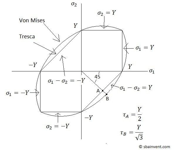
Next, we can use the distortion energy failure theory to find the resulting von Mises mid-range stress and the alternating stress by using the following equations.
Alternating Von Mises Stress
(Eq 11) $σ’_a=\left(σ_a^2+3τ_a^2\right)^{1/2}$
Midrange Von Mises Stress
(Eq 12) $σ’_m=\left(σ_m^2+3τ_m^2\right)^{1/2}$
Once you’ve solved for the Von Mises Stress you will now need to determine what the endurance limit is by using the equation below.
(Eq 13) $S_e=k_ak_bk_ck_ek_fS_e^{,2}$
The following article discusses in detail on how to find all of the values needed to find the endurance limit for the equation above.
Finally, once you know what the endurance limit is, and what you know what the Von Mises stresses are, you can solve for the safety factor. There are different methods that can be used to solve for the safety factor, and each will produce a slightly different answer.
The first criteria is the Soderberg criteria, which is represented by the equation below.
(Eq 14) $\frac{σ’_a}{S_e}+\frac{σ’_m}{S_y}=\frac{1}{n}$
$S_y$ = Yield Strength of the Material
Another criteria that could be used is the modified-Goodman criteria.
(Eq 15) $\frac{σ’_a}{S_e}+\frac{σ’_m}{S_{ut}}=\frac{1}{n}$
$S_{ut}$ = the Ultimate Strength of the Materials
The Gerber criteria is another method that can be used to find the safety factor.
(Eq 16) $\frac{nσ’_a}{S_e}+\left(\frac{nσ’_m}{S_{ut}}\right)^2=1$
A fourth criteria that can used is the ASME-elliptic criteria which is represented by the equation below.
(Eq 17) $\left(\frac{nσ’_a}{S_e}\right)^2+\left(\frac{nσ’_m}{S_{ut}}\right)^2=1$
Finally, the last criteria is the Langer Static criteria.
(Eq 18) $σ’_a+σ’_m=\frac{S_y}{n}$
To meet the above criteria n must be greater than or equal to 1 if it is less than 1 then the part is predicted to fail. Conservative designers will use the modified-Goodman criteria. Either way though the part must pass the Langer Static criteria otherwise the part is predicted to fail statically.
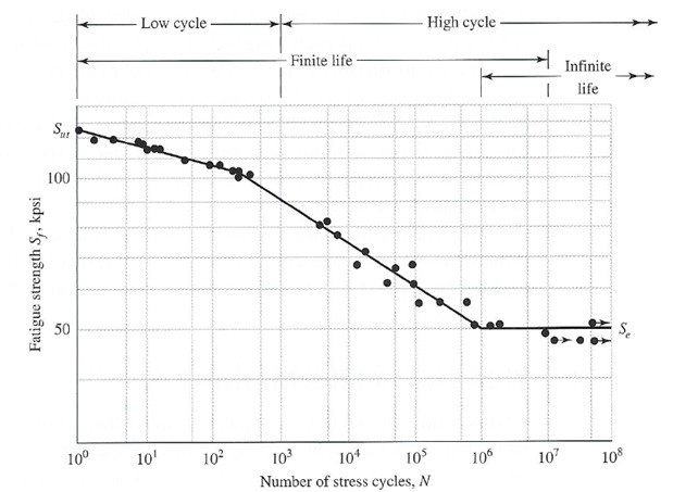
Finally, the endurance limit can used to predict the fatigue stress in relation to a certain number of cycles by using the following equations.
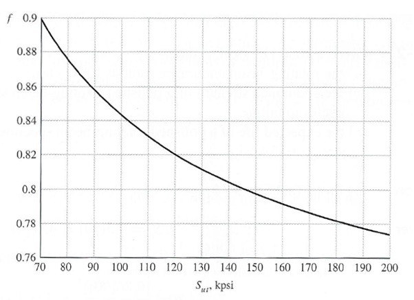
(Eq 19) $S_f=aN^b$
$N$ = number of Cycles
(Eq 20) $a=\frac{(fS{ut})^2}{S_e}$
(Eq 21) $b=-\frac{1}{3}log\left(\frac{fS{ut}}{S_e}\right)$
$f$ = fatigue strength fraction
The fatigue strength fraction can be found by using the following graph.
Determining Critical Stress Locations
Article Content Links: Shaft Materials, Shaft Layout, Torque Transmission, Calculating Static Stresses, Dynamic Stresses and Fatigue, Determining Critical Stress Locations, Deflection, Critical Speed
When analyzing shafts you do not need to analyze every point of a shaft, and from the above two sections you can see that this would be daunting task to do. Instead you should only focus on a few critical locations.
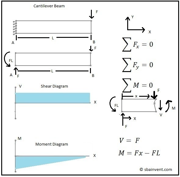
This first area that you should focus on is the outer surface of the shaft where the moment of the shaft is the greatest. For a shaft that is support like a cantilevered beam the moment will be at its greatest where the beam is supported. For a shaft that is supported on both ends you will need to create a moment diagram to find out where the greatest moment is.
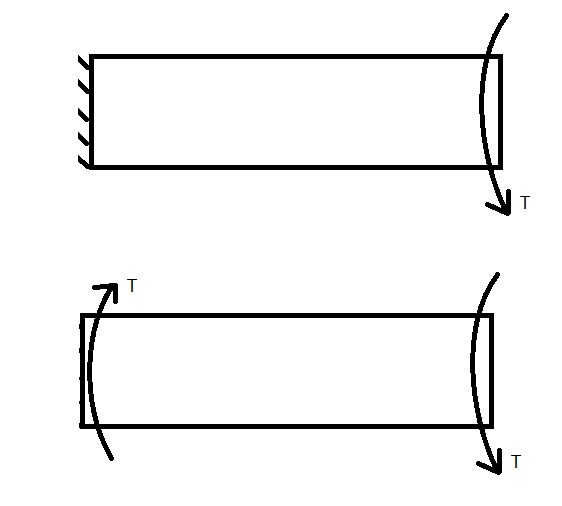
You will also want to focus on areas where torque in present. As mentioned above, a single torque will be constant between the component that is transmitting the torque and the component that the torque is being transmitted to. There could however be situations where there are multiple torques interacting on a shaft. This could cause some torques to cancel each other out and other torques to be added together. Again, to determine where the maximum torque would be on a shaft you will need to create a free body diagram.
Also, you should focus on areas of the shaft that have high stress concentrations that could amplify what might considered an insignificant stress into a stress that could cause failure.
When there is a bending moment there is a shear stress as well as a normal stress due to the moment. Generally, the shear stress caused by a moment is insignificant in comparison to normal stress caused by the moment. Due to this fact you may not even need to consider that shear stress in your analysis. The one case where you would want to consider it is when the bending moment is on a short stubby beam, which in those cases the shear stress could be significant when compared to the normal stress due to a bending moment. Also, remember if you are analyzing the shear stress due to the bending moment the maximum shear stress will be present at the centroid of the shaft, while it will be negligible on the surface of the shaft. This is the reverse for the normal stress due to bending as well as the shear stress due to torsion. In those cases the maximum stress will be on the surface of the shaft and is negligible at the centroid of the shaft.
Finally, the last type of force that could interact on a shaft is an axial force due to a thrust load. This generally can be considered negligible though in comparison to stress due to a bending moment, and the stress due to torsion. It depends, however, and you will need to make an educated decision based off the current information that you have at the time.
Deflection
Article Content Links: Shaft Materials, Shaft Layout, Torque Transmission, Calculating Static Stresses, Dynamic Stresses and Fatigue, Determining Critical Stress Locations, Deflection, Critical Speed
In addition to stresses, you might also be interested in the deflection caused by those stresses. One of the main reasons that you might be interested in determining what the deflection is on a shaft is to make sure northing binds. Remember the shaft could be seeing an axial load, a torsional load, or a bending moment, or combination of all three.
The easiest types of deflection to calculate will be the deflection due axial loading and the deflection due to torsional loading. The equation below would be used to calculate the deflection due to an axial load.
(Eq 22) $δ=\frac{FL}{AE}$
$L$ = Length between the force and ground
$E$ = Young’s Modulus
$A$ = cross-sectional area
The equation below would be used to calculate the angle of twist due to a torsional load.
(Eq 23) $Φ=\frac{TL}{JG}$
$L$ = the distance that the torque is applied to
$G$ = Shear Modulus
$J$ = Polar Moment of Inertia
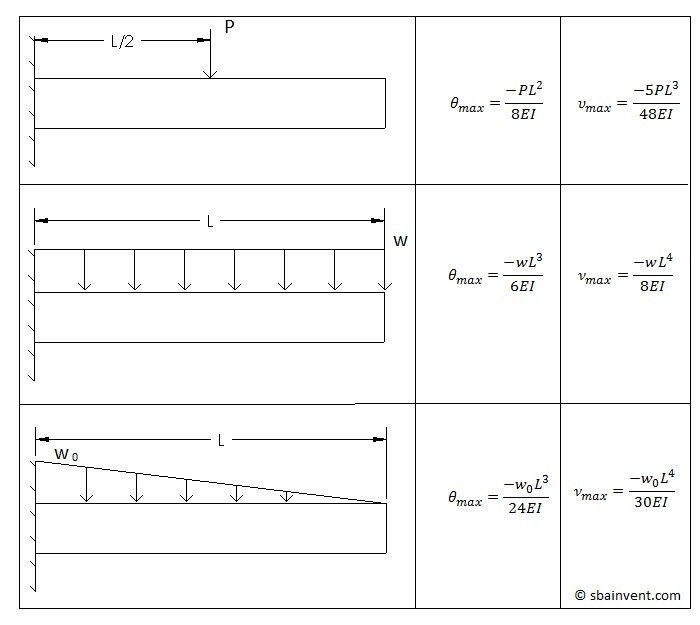
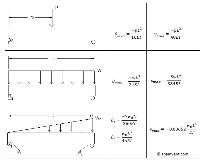
Next, the deflection due to a bending moment may need to be determined. This is much more complicated and a single equation can’t be used to find this. Instead you will need to derive the equations based off of the shear and moment diagrams. The images below provide six different examples that can used to calculate the total deflection of the shaft and its slope. You can however derive your own equations for unique situations by either using deflection by integration or by using the discontinuity functions.
Critical Speed
Article Content Links: Shaft Materials, Shaft Layout, Torque Transmission, Calculating Static Stresses, Dynamic Stresses and Fatigue, Determining Critical Stress Locations, Deflection, Critical Speed
As a shaft rotates its rigidity EI resists centrifugal forces caused by the shafts rotation. These deflection are typically small, and do not cause any issues with the assembly. However, there are certain speeds when the shaft can become unstable, and the deflection will increase without any upper bound to stop them. This is known as the critical speed or natural frequency of the shaft. If the shaft is a simple uniform diameter the following equation can be used to find the first critical speed of the shaft.
(Eq 24) $ω_1=\left(\frac{π}{l}\right)^2\sqrt{\frac{EI}{m}}$
$m$ = mass per unit length
To find the higher order critical speeds you will need to use matrix algebra, which I’m not going discuss in this article, or use computer modeling.