Gear Ratios
(Eq 1) $P=Tω$
From equation 1 the concept of a gear ratio can be derived. This means that if you know what your current torque and speed are, and have a certain torque you want to convert this to, you can use a gear ratio to determine the change in angular velocity to obtain this new torque. Refer to equation 2. Keep in mind this equation assumes that there is no loss in power through the gear train, meaning the gear train is 100% efficient, which is impossible in real life.
(Eq 2) $\frac{T_1}{T_2}=\frac{ω_1}{ω_2}$
The above equation is not the only way to determine the gear ratio. Depending on what information you know at the time, there are different methods that can be used to determine the gear ratio. Refer to equation 3 for different methods to determine the gear ratio.
(Eq 3) $gear~ratio = \frac{(rpm)_1}{(rpm)_2}=\frac{r_2}{r_1}=\frac{(gear~teeth)_2}{(gear~teeth)_1}$
Notice from equation 3 there are different methods to determine the gear ratio. Also, from this equation, it can be seen that the size difference between the two gears can determine the gear ratio. This can be proven using statics by stating that the two gears are fixed. Refer to the example below.
Example
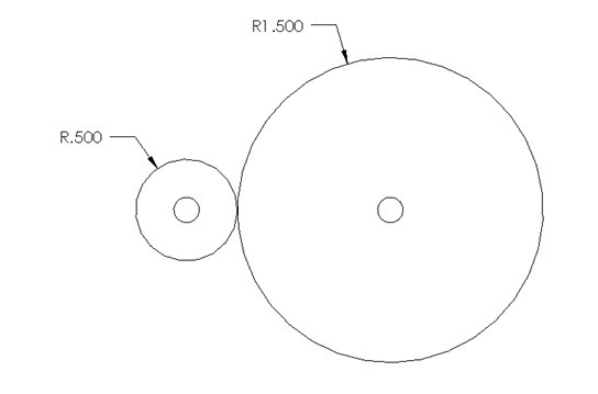
Determine Torque using Statics
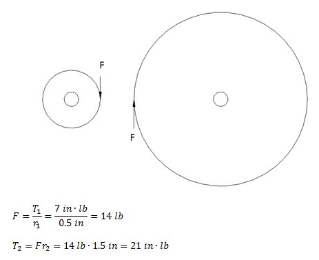
$F=\frac{T_1}{r_1}=\frac{7in·lb}{0.5in}=14lb$
$T_2=Fr_2=14lb·1.5in=21in·lb$
Determine Torque using Gear Ratio
$gear~ratio=\frac{r_2}{r_1}=\frac{1.5}{.5}=3$
$T_2=T_1(gear~ratio)=(7in·lb)(3)=21in·lb$
Determine RPM of Large Gear
$(rpm)_2=\frac{(rpm)_1}{gear~ratio}=\frac{1000RPM}{3}=333.3RPM$
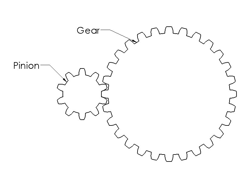
Gear Nomenclature
A simple two gear system consists of two gears. Typically one gear is smaller while the other is larger. The smaller gear is normally called the pinion, while the larger gear is called the gear. Refer to the figure below.
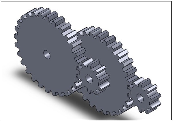
Gear Train
A meshing pinion and gear is often referred to as a gear train. It is possible to include multiple pinions and gears within a gear train to increase the gear ratio while compacting the design. Refer to the figure below.
Gear Tooth Nomenclature
Do to the complexity of a gear tooth a nomenclature has been developed to describe the different parts of the tooth. Refer to the image below .
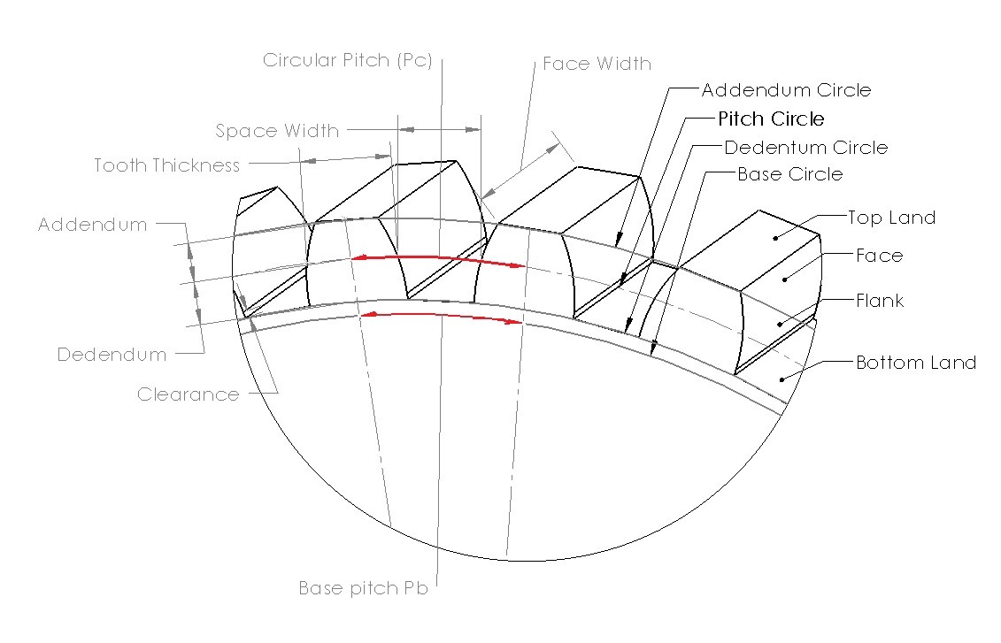
(Eq 4) $p_c=\frac{πd}{N}$
The base pitch can be determined by using the equation below.
(Eq 5) $p_b=p_ccosΦ$
Finally, the diametral pitch can be determined by using equation 6.
(Eq 6) $P_d=\frac{π}{P_c}=\frac{N}{d}$
The diametral pitch must be the same for both the pinion and gear for the two to mate correctly. Refer to the table below to determine the dimensional values of a gear tooth based off of the AGMA (American Gear Manufacturers Association) specifications.

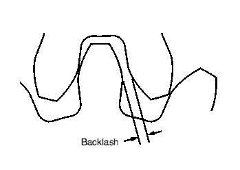
Backlash
Backlash in mating gears is caused by the clearance between the mating teeth of the two gears. The clearance is due to manufacturing tolerances that are set. Manufacturing tolerances are unavoidable since it is impossible to make every gear tooth exact. So in turn there must be some small clearance between the gear teeth so that the gears can mesh correctly without jamming.
If the gears are ran in one direction backlash normally will not be noticeable. However, when that direction is reversed, the gear teeth will impact each other causing considerable noise. This not only can cause significant stresses and wear on the gears. It can also cause positional error on the gears. This in turn could further the wear on the gears. Finally, as the gears age the clearance between the gear teeth will normally increase, causing more backlash. This can cause issues with machinery that rely on precision.
To help counter the effects of backlash on the precision applications. Servomechanisms can be used to track position of the part of the machine the gears are moving. However, backlash can also be stopped through mechanical means by using antibacklash gears. An antibacklash gear is simply two gears back-to-back on the same shaft that have been rotated slightly during assembly with respect to each other to minimize backlash to the system.
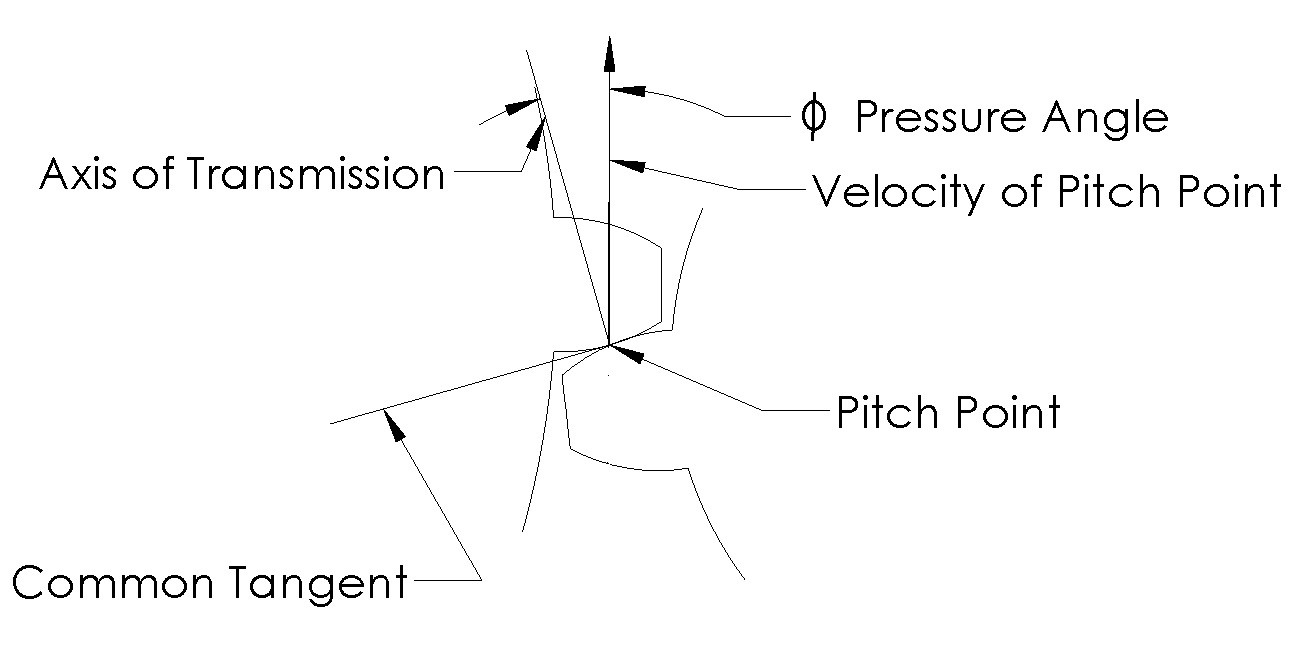
Pressure Angle
The pressure angle of gear is the angel between the axis of transmission of the gear and the direction of the velocity of at the pitch point. For gears the pressure angle is standardized at 14.5°, 20°, and 25°. However the most common pressure angle is 20°. Mating gears must be cut to the same nominal pressure angle.
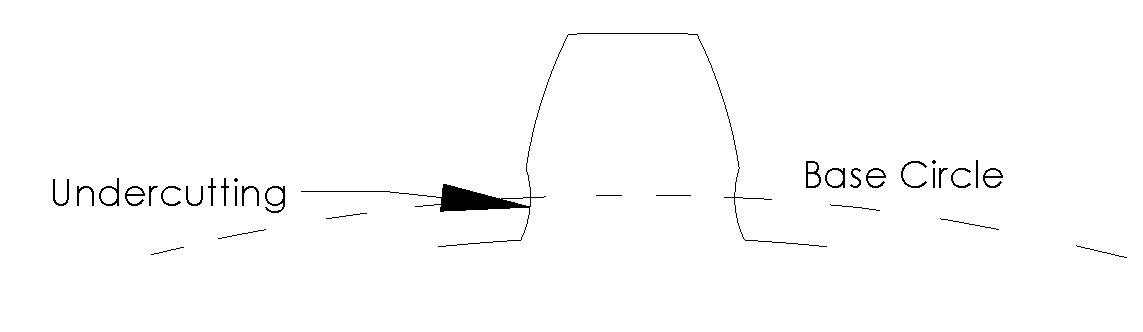
If the dedendum of a gear tooth is large enough to extend below base circle interference will most likely occur between the two mating gears, which will cause the tip of one tooth to start to cut away material from the other tooth’s root. This is known as undercutting.
Undercutting should be avoided due to the fact that tooth that has material removed from its root will become weaker. This could severely lower that tooth’s maximum moment and shear force, increasing the chances that the tooth could fail at a much lower load than expected.
A way to avoid undercutting is to avoid gears that have too few teeth. When a gear has a large number of teeth, those teeth will be comparably smaller in comparison to the actual diameter of the gear lowering the chances of undercutting. While as the number of teeth are reduced on a gear, the dedendum of the tooth will increase in length until undercutting occurs.
Spur gear, helical gears, herringbone are very similar except for how the teeth are cut.
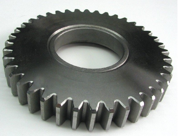
Spur Gear
A spur gear is one of the simplest, most common, and least expensive gear made. It essentially is cylinder that has teeth cut parallel to the axis of the gear. Refer to the image below. For a pinion and gear to mesh, the axis of both gears must be parallel.
Helical Gears
A helical gears teeth are cut at a certain angle with respect to the axis of the gear. By cutting the gear like this, the gear and pinion can mesh parallel to their axis or they can be meshed at an offset angle dependent on the angle of the teeth on the gears. Refer to the image below.
Due to the additional friction between the gear teeth there is a loss of efficiency for helical gears in comparison to spur gears. A parallel helical gear set has an efficiency of 96-98%, while helical gears that are crossed (set at an angle) have an efficiency of 50 to 90% depending on the angle.
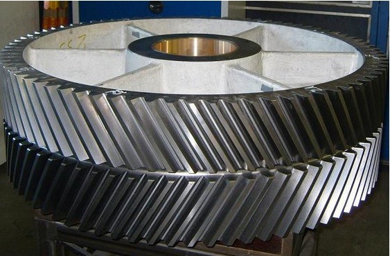
Herringbone Gears
Herringbone gears are essentially two helical gears of identical pitch and diameter that are joined together. This provides an advantage over a helical gear because the thrust load on the gear will be canceled, which means thrust bearings will not be needed in the design. These gears are very expensive to make however and are normally only used for large, high-power applications. Refer to the image below.
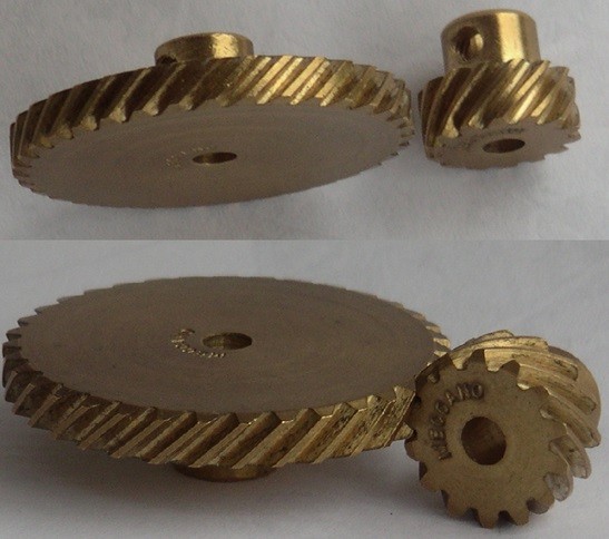
Worm Gears
A wormset consists of two different types of gears, the worm and the worm gear. The worm is the gear that has only one tooth that is continuously wrapped around its circumference a certain number of times. The worm will mesh to the worm gear perpendicularly. Refer to the image below.
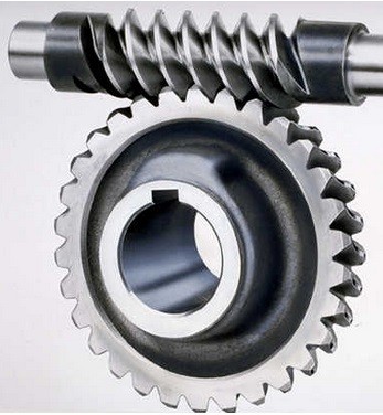
Another advantage of a wormset is that they are impossible to backdrive. This means that the worm can drive the worm gear but the worm gear cannot drive the worm providing convenient locking mechanism. However because of this there are large sliding and thrust loads, which will cause a wormset can be rather inefficient with an average efficiency of 40 to 85%.
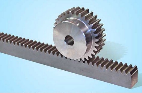
Rack and Pinion
A rack and pinion consists of a pinion gear and a linear gear called the rack. The teeth of rack are similar to that of a spur gear, except the teeth on the rack are basic trapezoids making it easy to create a tool to cut these. Refer to the image below.
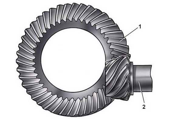
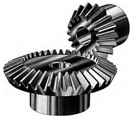
Bevel Gears
Bevel gears are gears that are designed to change the angle of the drive. Refer to the image below.
Hypoid Gears
A hypoid gear is a special type of bevel gear that will allow the two gears to mesh when the axis of the gears are nonparallel and nonintersecting. A regular bevel gear from the image above would not be able to mesh under these conditions. The teeth of a hypoid gear are based off of rolling hyperboloids allowing the two gears to mesh under the conditions stated above. Refer to the image below to see a hypoid gear.