There are three basic types of control volumes. They are fixed non-deforming control volumes, moving control volumes, and deforming control volumes.

Fixed, Non-deforming Control Volume
The first type of control volume that I will discuss in the fixed, non-deforming control volume. Generally, this type of control volume is the type that is used for most fluid mechanics problems. First, let’s take a look at the general form of the continuity equation.
(Eq 1) $\frac{∂}{∂t}\int{_{CV}}ρdV+\int{_{CS}}ρv·\hat{n}dA = 0$
$ρ$ = density
$V$ = volume
$v$ = velocity
$A$ = cross-sectional area
Equation 1 is derived through a combination of the conservation of mass and the Reynolds transport theorem. First, conservation of mass states that the rate of change of a system’s mass must equal 0. In addition, the Reynolds transport theorem is the bridge between system and control volume analysis. As a result the dot product ($v·\hat{n}$), is positive “+” when mass enters the control volume but negative “-” when it exits. Also, if the the flow is steady, than the mass contents within the control volume will be the following.
$\frac{∂}{∂t}\int{_{CV}}ρdV=0$
Hence, by the conservation of mass, the mass entering the control volume will equal the mass exiting the control volume. From this the mass flowrate equation is derived.
(Eq 2) $\sum{ρ_1v_1A_1} =\sum{ρ_2v_2A_2}$
or
$\sum{\dot{m}_{out}} = \sum{\dot{m}_{in}}$
In addition, if the flow is also incompressible, than the density “ρ” does not need to be included in equation 2. In turn, this will result in the volume flow rate.
(Eq 3) $\sum{Q_{out}} = \sum{Q_{in}}$
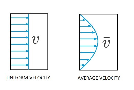
Finally, the velocity “$v$” in equation 2 and 3 represents a velocity profile that is uniformly distributed over the opening on the control surface. Hence if the velocity profile is not uniformly distributed the variable “$v$” will need be replaced with the average velocity “$\bar{v}$”.

Moving Control Volume
In addition to fixed control volumes, there can also be cases when you need to use a moving control volume. An example of when a moving control volume would be needed is when you are analyzing a jet engine. This can seen in the image at the top of the page.
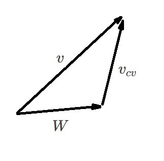
In order to analyze a moving control volume you will need to use relative motion. As a result there will be a relative velocity and an absolute velocity. The relative velocity will be the velocity of the fluid moving through control volume observed by an observer moving with the control volume. On the other hand the absolute velocity is observed at a fixed point in space by an observer. This can be described by the following vector equation.
(Eq 4) $v = W + v_{cv}$
$W$ = relative velocity
$v_{cv}$ = the control volumes velocity
$v$ = absolute velocity

Taking this into consideration equation 1 can be modified to the following.
(Eq 5) $\frac{∂}{∂t}\int{_{CV}}ρdV+\int{_{CS}}ρW·\hat{n}dA = 0$
If the moving control volume is also non-deforming the dot product sign convection used for a non-deforming fixed control volume will apply. In addition if the fluid moving through the control volume is steady than $\frac{∂}{∂t}\int{_{CV}}ρdV$ will equal zero.
Deforming Control Volume
Finally, you may need to use a deforming control volume to solve a problem. An example of when a deforming control volume would be used is when you are analyzing a deflating balloon. When you are analyzing deforming control volume the following form of the continuity equation would need to be used.
(Eq 6) $\frac{DM_{sys}}{Dt}=\frac{∂}{∂t}\int{_{CV}}ρdV+\int{_{CS}}ρW·\hat{n}dA = 0$
In this case, however, $\frac{∂}{∂t}\int{_{CV}}ρdV$ will normally be a non-zero value, which means it will need to remain part of the equation. Because of this you will need to be careful how you evaluate it. The second part of the equation, $\int{_{CS}}ρW·\hat{n}dA$, as before determines the mass flow rate. The relative velocity “W” will need to be used if the deforming control volume is moving as was discussed in non-deforming, moving control volume section.