There are a number of steady flow engineering devices. For instance there are nozzles and diffusers, as well as pumps and compressors. To understand what a steady flow engineering device is you will need to have to have an understanding of what a steady flow process is.
Briefly I will describe what a steady flow process is. First, during a steady flow process, the fluid will flow through the control volume steadily. As a result, the mass flow will be constant. In addition, during a steady state process any intensive or extensive properties will remain constant. Hence, specific volume, internal energy, etc would remain constant at a specified point. This doesn’t mean it can’t be different at different points within the system. Refer to the equation below.
(Eq 1) $∑\dot{E}_{in}=∑\dot{E}_{out}\rightarrow\dot{Q}_{in}$$+\dot{W}_{in}+∑\dot{m}_{in}θ=\dot{Q}_{out}+\dot{W}_{out}+∑\dot{m}_{out}θ$
$\dot{Q}$ = Rate of Heat Transfer
$\dot{W}$ =Rate of Work
$\dot{m}$ = mass flow
(Eq 2) $θ=h+\frac{v^2}{2}+gz$
$h$ = enthalpy
$v$ = velocity
$g$ = gravitational constant
$z$ = elevation
Finally, the boundary work has to be zero. This doesn’t mean that there can’t be other aspects that require work, or produce work. For example shaft work is required to turn the blades of a turbine.
Steady Flow Engineering Devices
For a device to be considered a steady flow device it must be able to operate under the same conditions for a long period of time. There are a number of steady flow devices. For instance there are Nozzles & Diffusers, Turbines & Compressors, Throttling Valves, and Heat Exchangers & Mixing Chambers.
Nozzles & Diffusers
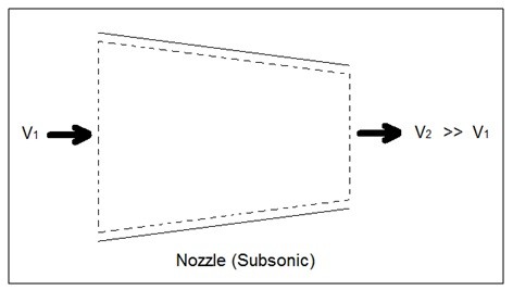
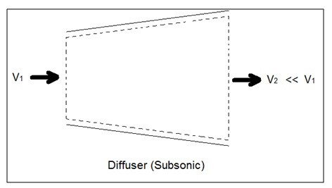
Nozzles are steady flow engineering devices that are used to increase a fluids velocity at the expense of pressure. For subsonic flows a nozzle will have a wider cross-sectional area at its entrance. The cross-sectional area will slope to a smaller cross-sectional area at its exit. On the other hand when the flow is supersonic, the entrance cross-sectional will be smaller than the exit cross-sectional area. The image below shows a basic subsonic nozzle.
(Eq 3) $\dot{E}_{in}-\dot{E}_{out}=\dot{m}\left[\left(h_{in}+\frac{v^2_{in}}{2}\right) – \left(h_{out}+\frac{v^2_{out}}{2}\right) \right]$
Turbines
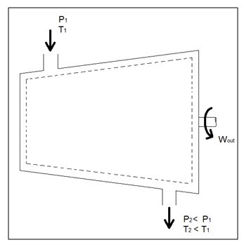
Turbines are steady flow engineering devices that rely on shaft work to drive an electric generator. They are found in steam, gas, and hydrostatic power plants. Heat transfer is negligible. In addition, potential energy is negligible unless otherwise stated. Finally, even though kinetic energy is present within the system, the change in enthalpy is normally much greater. As a result, kinetic energy is also negligible.
During operation super heated steam will be pushed through the turbine. As this is occurring it is possible that the steam could become a saturated gas when it leaves. This must be taken into consideration when you are calculating the exit enthalpy. Finally, liquids can damage the blades of a turbine. As a result, it is best to keep a fluid in a gas state as it passes through the turbine.
The equation below represents the basic energy balance for a turbine.
(Eq 4) $\dot{E}_{in}=\dot{E}_{out}\rightarrow\dot{m}h_{in}=\dot{W}_{out}+\dot{m}h_{out}$
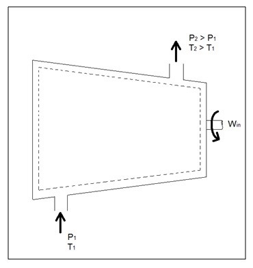
Compressors
A compressor, unlike a turbine, is a steady flow engineering device that uses shaft work to create power. Hence, shaft work is required to run a compressor. In addition, heat transfer, as well as potential and kinetic energy are negligible. The equation below represents the basic energy balance for a compressor.
(Eq 5) $\dot{E}_{in}=\dot{E}_{out}\rightarrow\dot{W}_{in}+\dot{m}h_{in}=\dot{m}h_{out}$
Other devices that are similar to compressors are fans and pumps. There are, however, some application differences between these devices. For instance, a fan does not raise the pressure of a fluid to a high pressure. Instead it will mobilize a gas. Pumps, on the other hand, are used to move or pressurize liquids. Pumps can only be used for liquids, while compressors can only be used on gases. If a pump tried to pump a gas it could be damaged. The same goes for a compressor, if it were used to compress a liquid it would most likely ruin the compressor.
Throttling Valves
A throttling valve is a steady flow engineering device that is used to restrict flow. A considerable pressure drop will result from the restricted flow. In turn, a large temperature drop will result. Hence, throttling valves are widely used in refrigeration devices. There are many devices that can be considered throttling valves. Some examples are porous plugs, capillary tubes, and adjustable valves.
Fluid flowing through a throttling valve undergoes an adiabatic process. In addition, no work is done and potential energy is negligible. Kinetic energy is also negligible even though there is a large change in velocity. Instead change in internal energy is much more pronounced in comparison to kinetic energy. Finally, enthalpy values at the entrance and exit of the throttling valve are approximately the same. Taking all of this into consideration the following energy balance equation for a throttling valve will result.
(Eq 6) $\dot{E}_{in}=\dot{E}_{out}\rightarrow\dot{W}_{in}+\dot{m}h_{in}=\dot{m}h_{out}$
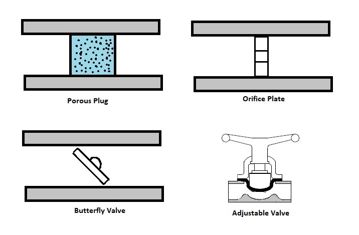
Types of Throttling Valves
Throttling valves are very simple steady flow engineering devices. As mentioned above throttling valves can be a porous plug, capillary tubes put in between two large tubes, or simply an adjustable valve like a ball valve. The whole point is to restrict the flow to drastically drop the pressure which will cause a large temperature drop within the fluid. Refer to the image below to see different types of throttling valves.
For a fun fact, besides refrigerators, another common device that uses a throttling valve is the carburetor in a small engine. The throttling valve in a small engine is not there to adjust the temperature of the gas. Instead it is used to control the amount of air that will mix with the gas to control combustion. If there isn’t enough air, the engine will run rich causing poor fuel economy. On the other hand, if there is too much air, the engine will run lean. This will cause the engine to produce more heat. As a result, less power will be produced.
The type of valve used on a carburetor is typically a butterfly valve. The throttling valve is normally controlled by the choke. Closing the choke purposely causes the engine to run rich. This is done to make it easier to start the engine. The choke is than opened to allow optimal running conditions once the engine has warmed up. The stoichiometric air-fuel ratio which 14.7 lb of for ever 1 lb of fuel is the ideal air to fuel ratio for lowest emission, however, the best ratio for power is 12.5 lb of air for 1 lb of fuel.
Mixing Chambers
Mixing chamber are steady flow engineering devices that mix two streams of fluid to cause a temperature change. The temperature alteration is highly dependent on the mass flow of the two streams in comparison to each other.
When solving for these types of problems the conservation of mass must be taken into consideration. For this device the mass of fluid entering must equal the mass of fluid exiting. In addition, how well insulated the device is must be considered. A well insulated device will have negligible heat transfer to the outside environment. Finally, both potential and kinetic energy are negligible. Taking all of this into consideration the following energy balance is used for a well insulated mixing chamber.
(Eq 7) $E_{in}=E_{out}\rightarrow\dot{m}_1h_1+\dot{m}_2h_2=\left(\dot{m}_1+\dot{m}_2\right)h_3$
Heat Exchangers
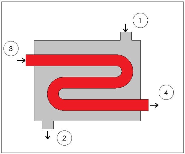
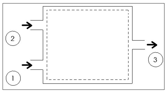
Heat exchangers are similar to mixing chambers except they do not allow the two streams of fluid to mix. As a result, the mass flow entering each pipe will remain constant. In addition, for well insulated heat exchangers heat transfer can be considered negligible. In addition, kinetic and potential energy as well as work is negligible. The following energy balance equation is used for a well insulating heat exchanger.
(Eq 8) $E_{in}=E_{out}\rightarrow\dot{m}_1h_1+\dot{m}_3h_3=\dot{m}_2h_2+\dot{m}_4h_4$
This equation is meant for a heat exchanger scene in the image below. If the heat exchanger you are looking at is different you may have to modify equation 8.