As heat is transferred from a one fluid to another fluid in a heat exchanger the temperature of one fluid will begin to rise as it passes through the heat exchanger while the other fluids temperature will begin to fall. This will cause the temperature difference between the two fluids to be different depending on what section of the heat exchanger is being analyzed. This means that the equation given in the opening article on heat exchangers will have some inaccuracies in the end calculation for heat transfer. Refer to the equation below.
(Eq 1) $q=UAΔT_{overall}$
U = Overall heat transfer coefficient
A = surface area for heat transfer consistent with the definition of U
Now let’s take a look at a simple two pipe heat exchanger. Refer to the image below.
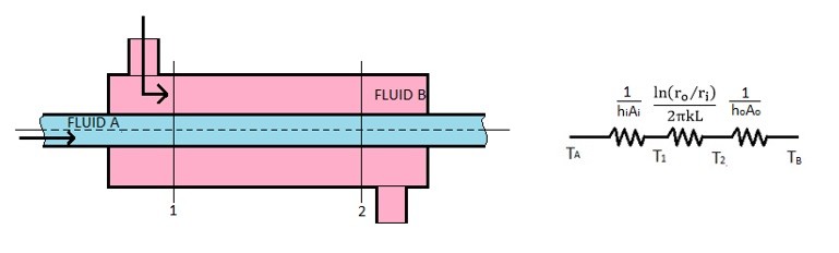
A two pipe heat exchanger can have a parallel flow between the two fluids or a counter flow between the two fluids. In the above image the fluid has a parallel flow since the fluid in the inner pipe is flowing in the same direction as the fluid in the outer pipe. On the other hand counter flow means that the fluids in the two pipes are flowing in the opposite direction.
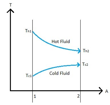
Refer to the image below to see the temperature profile between two fluids in a simple two pipe heat exchanger that have a parallel flow.
Refer to the image below to see the temperature profile for the two fluids in a simple two pipe heat exchanger that have a counter flow.
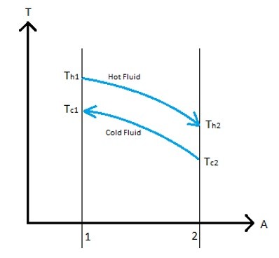
Notice for both temperature profiles there is an input and output temperature for each fluid. If you know these temperatures you can solve for the heat added to one fluid and lost by the other fluid using the following equation.
(Eq 2) $dq = -\dot{m}_hc_h(T_{h1}-T_{h2}) = \dot{m}_cc_c(T_{c1}-T_{c2})$
$\dot{m}$ = mass flow rate
c = specific heat
Also, by knowing the input temperatures and output temperatures of both the hot and cold fluid you can solve for the log mean temperature difference of the heat exchanger (LMTD) by using the following equation .
(Eq 3) $ΔT_m = \frac{(T_{h2}-T_{c2})-(T_{h1}-T_{c1})}{ln[(T_{h2}-T_{c2})/(T_{h1}-T_{c1})]}$
Once the LMTD of the heat exchanger is known equation 1 can be modified to the following equation.
(Eq 4) $q=UAΔT_m$
The above equation will provide a more accurate estimate of the heat transfer occurring between the two fluids in a heat exchanger, since it takes in consideration that there is a temperature profile between the two fluids.
There are few assumptions that are made when using the LMTD method. First off, it is assumed that the specific heats of the fluids do not vary with temperature. Another assumption that is made is that the convective heat transfer coefficient is the same throughout the entire heat exchanger. The second assumption is important to note because the entrance effects and fluid viscosity can have an effect on the convective heat transfer coefficient. Finally, equation 3 was derived using a simple two pipe heat exchanger that only has one shell pass and one tube pass. Note, the shell represents the outer pipe, while the tube represents the inner pipe. If there are more than one shell pass or tube pass a correction factor will need to be added to equation 4 to take this into account. Refer to the equation below.
(Eq 5) $q=UAFΔT_m$
F = correction factor
Experimental data can be used to determine what the correction factor would be, and most Heat Transfer text books will provide graphs that can be used to determine the correction factor for certain cases.