When heat is conducted through a body it is normally than removed through a convective process. This could be water flowing through a heat exchanger, air blowing over a flat plate or air blow over fins that are extruding out of a surface. In this section I will be discussing fins.
Fins are long slender pieces of material that extend a set distance out of a surface. The purpose of a fin is to increase the rate of heat transfer into the fluid that is flowing around the fin. The whole purpose of a fin is to increase the surface area that the fluid is flowing around to increase the rate of convection. Below is an image of a single fin.
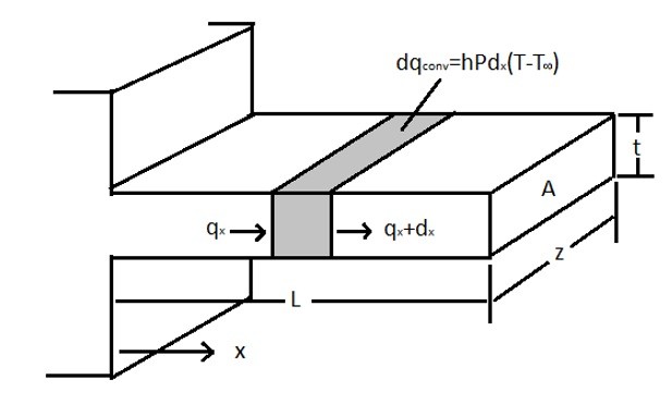
From the above image it can be seen that the heat transfer through a fin is both convective and conductive. It can also be seen that as the distance from the base of the fin is increased the rate of heat flowing through the fin decreases due to heat being taken away due to convection and the increase in conductive resistance. Basically what is happening is the differential surface area for convection becomes a product of the perimeter (P) of the fin and the differential length dx. This will result in the following energy balance equation for the fin.
(Eq 1) $\frac{d^2T}{dx^2}-\frac{hP}{kA}(T-T_∞)=0$
Let θ = T – T∞
(Eq 2) $\frac{d^2T}{dx^2}-\frac{hP}{kA}(θ)=0$
Using differential equations the general equation for equation 2 will be the following.
(Eq 3) $θ=C_1e^{-mx}+C_2^{mx}$
where $m=\sqrt{hp/kA}$
Now there are three general cases that a fin could be under that need to be considered.
Case 1: A fin that is very long resulting in the end of the fin be the same temperature of the surrounding fluid.
The boundary conditions for case 1 would be the following.
$θ = θ_o$ at $x = 0$ and $θ = 0$ at $x = ∞$
Using the above boundary conditions for Case 1 the solution for equation 3 will be the following.
(Eq 4) $\frac{θ}{θ_o}=\frac{e^{-mx}}{1+e^{-2mL}}+\frac{e^{mx}}{1+e^{2mL}}=\frac{cosh[m(L-x)]}{coshmL}$
The resulting heat transfer than would be the following.
(Eq 5) $q=\sqrt{hPkA}θ_o$
Case 2: The end of the fine is insulated so that no heat transfer out of the tip of the fin.
The boundary conditions for Case 2 would be the following.
$θ = θ_o$ at $x = 0$ and $\frac{dθ}{dx} = 0$ at $x = L$
Using the above boundary conditions for Case 2 the solution for equation 3 will be the following.
(Eq 6) $\frac{θ}{θ_o}=\frac{e^{-mx}}{1+e^{-2mL}}+\frac{e^{mx}}{1+e^{2mL}}=\frac{cosh[m(L-x)]}{cosh(mL)}$
The resulting heat transfer would then be the following.
(Eq 7) $q=\sqrt{hPkA}θ_otanh(mL)$
Case 3: The length of the fin is finite and loses heat through convection from its end.
The resulting equation for case 3 would be the following.
(Eq 8) $\frac{T-T_∞}{T_o-T_∞}=\frac{cosh[m(L-x)]+(h/mk)sinh[m(L-x)]}{cosh[mL]+(h/mk)sinh[mL]}$
The resulting heat transfer than would be the following.
(Eq 9) $q=\sqrt{hPkA}(T_o-T_∞)\frac{sinh[mL]+(h/mk)cosh[mL]}{cosh[mL]+(h/mk)sinh[mL]}$
Fin Efficiency
From the above proofs it is seen that a fins efficiency in transferring heat lessens as the fin length increases. This can be represented by a fin efficiency in transferring heat. Being able to find the fin efficiency of a fin will greatly reduce the complexity in solving the total heat transfer for a fin. The equation below represents the fin efficiency.
(Eq 10) $Fin efficiency = \frac{actual heat transferred}{heat transferred fin at base temperature}=η_f$
The following graphs can be used to determine the fin efficiency for various situations.
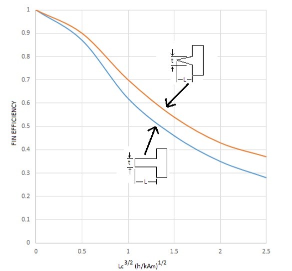
The first graph represents a straight rectangular and straight triangular fin. From the graphs it can be seen that a triangular fin is more efficient than a rectangular fin. The reason why is because the triangular fin lowers its thermal resistance as it become longer, which allows for more of the heat to transfer to the surface to be taken away through convection. To use this graph the following equations will be used.
(Eq 11) $L_C = \cases{ L+\frac{t}{2} & rectangular \cr L & triangular}$
(Eq 12) $A_m = \cases{ tL_C & rectangular \cr \frac{t}{2}L_c & triangular}$
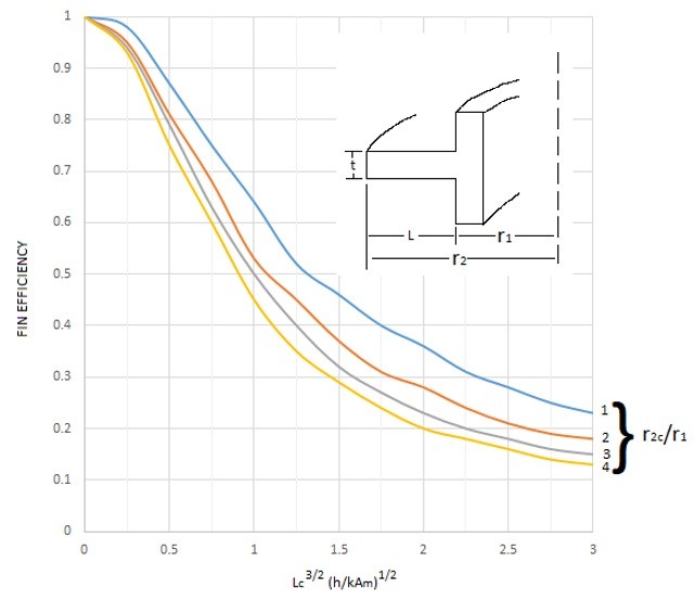
The second graph on the other hand represents a circumferential rectangular fin. In order to use this graph the following equations will be needed.
(Eq 13) $L=r_2-r_1$
(Eq 14) $L_C=L+\frac{t}{2}$
(Eq 15) $r_{2c}=r_1+L_C$
(Eq 16) $A_m=tL_C$
Now that the fin efficiency can be found, this follow can now be used to find the total heat transfer due to convection. Refer to the equation below.
(Eq 17) $q_f = η_fA_fhθ_o=\frac{θ_o}{R_f}$
(Eq 18) $A_f=PL$
The fins heat transfer resistance can be expressed as the following equation.
(Eq 19) $R_f=\frac{1}{η_fA_fh}$
Now all of this needs to be implemented onto a fin wall combination, as seen in the image below.
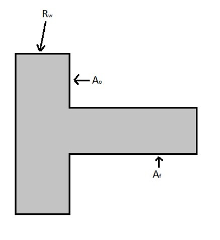
For the fin portion the heat transfer would be represented by the following equation.
(Eq 20) $q_f = \frac{T_i-T_∞}{R_{wf}+R_f}$
Where Rwf is the resistance of the wall under the fin.
For the portion of the wall that doesn’t have a fin coming out of it the heat transfer equation would be the following.
(Eq 21) $q_o = \frac{T_i-T_∞}{R_{wo}+R_o}$
where
(Eq 22) $R_o=\frac{1}{hA_o}$
Finally, the total heat transfer through the fin wall combination can be found using the following equation.
(Eq 23) $q_{total}=q_f+q_o$