Heat exchangers are devices that are designed to transfer heat from once fluid into another fluid without the two fluids mixing. An example of this is the radiator in your car. The coolant in the radiator is ran through the engine block pulling heat from the engine. That coolant is than sent to the radiator where the fluid passes through tubing that has air flowing over it driven by the radiators fan. The cooled coolant is than sent back into the engine to remove more heat from the engine and the process repeats.
In the above example the radiator acts as a heat exchanger by providing a way for the air to remove heat from the coolant without the air physically touching the coolant, causing a potential environmental hazard. Below is an image showing a simple example of a heat exchanger.
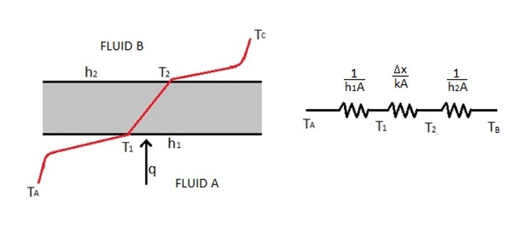
The above image shows heat be exchanged from fluid A to fluid B as it is passed through a flat plate. To solve for the total heat being exchanged between the two fluids the following equation would be used.
(Eq 1) $q=\frac{T_A-T_B}{\frac{1}{h_1A}+\frac{Δx}{kA}+\frac{1}{h_2A}}$
h = convective heat transfer coefficient
k = the thermal conductivity of the plate
x = the thickness of the plate
If the overall heat transfer coefficient (U) of the heat exchanger is known than equation 1 can be simplified to the following.
(Eq 2) $q=UAΔT_{overall}$
Generally, a heat exchanger will be composed of a series of cylindrical tubes not flat plates as seen in the above example. The image below shows a simple two tube heat exchanger.
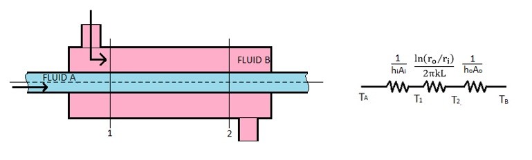
For the example above, there is a fluid flowing through an inner tube and fluid flowing over the inner tube. This means that all of the heat transfer will be occurring through the walls of the inner tube assuming the walls of the outer tube are insulated. To determine the heat transfer through the walls of the inner tube the equation below would be used.
(Eq 3) $q=\frac{T_A-T_B}{\frac{1}{h_iA_i}+\frac{ln(r_o/r_i)}{2πkL}+\frac{1}{h_oA_o}}$
For the above example the overall heat transfer coefficient can pertain to either the inside or the outside of the tube depending on the choice of the designer. The inside of the tube will be represented by subscript i and the outside of the tube will be represented by subscript o. Refer to the equations below to calculate the overall heat transfer coefficient for a simple two tube heat exchanger.
(Eq 4) $U_i = \frac{1}{\frac{1}{h_i}+\frac{A_iln(r_o/r_i)}{2πkL}+\frac{1}{h_o}}$
(Eq 5) $U_o=\frac{1}{\frac{A_o}{A_ih_i}+\frac{A_oln(r_o/r_i)}{2πkL}+\frac{1}{h_o}}$
Fouling Factor
As time progresses the surfaces inside a heat exchanger can start to build up deposits that will lower the amount of heat that the heat exchanger will be able to transfer due to the added thermal resistance. This is known as the fouling factor. To calculate the fouling factor the equation below would be used.
(Eq 6) $R_F = \frac{1}{U_{dirty}}-\frac{1}{U_{clean}}$
The following table provides examples of fouling factors for certain conditions. Once the fouling factor is determine, and the overall heat transfer coefficient for a clean surface is determined, the overall heat transfer coefficient for a dirty surface can then be determined. Equation 2 can be used to predict the total heat transfer for a heat exchanger once deposits start to build up on its surfaces.
m2–oC/W |
|